
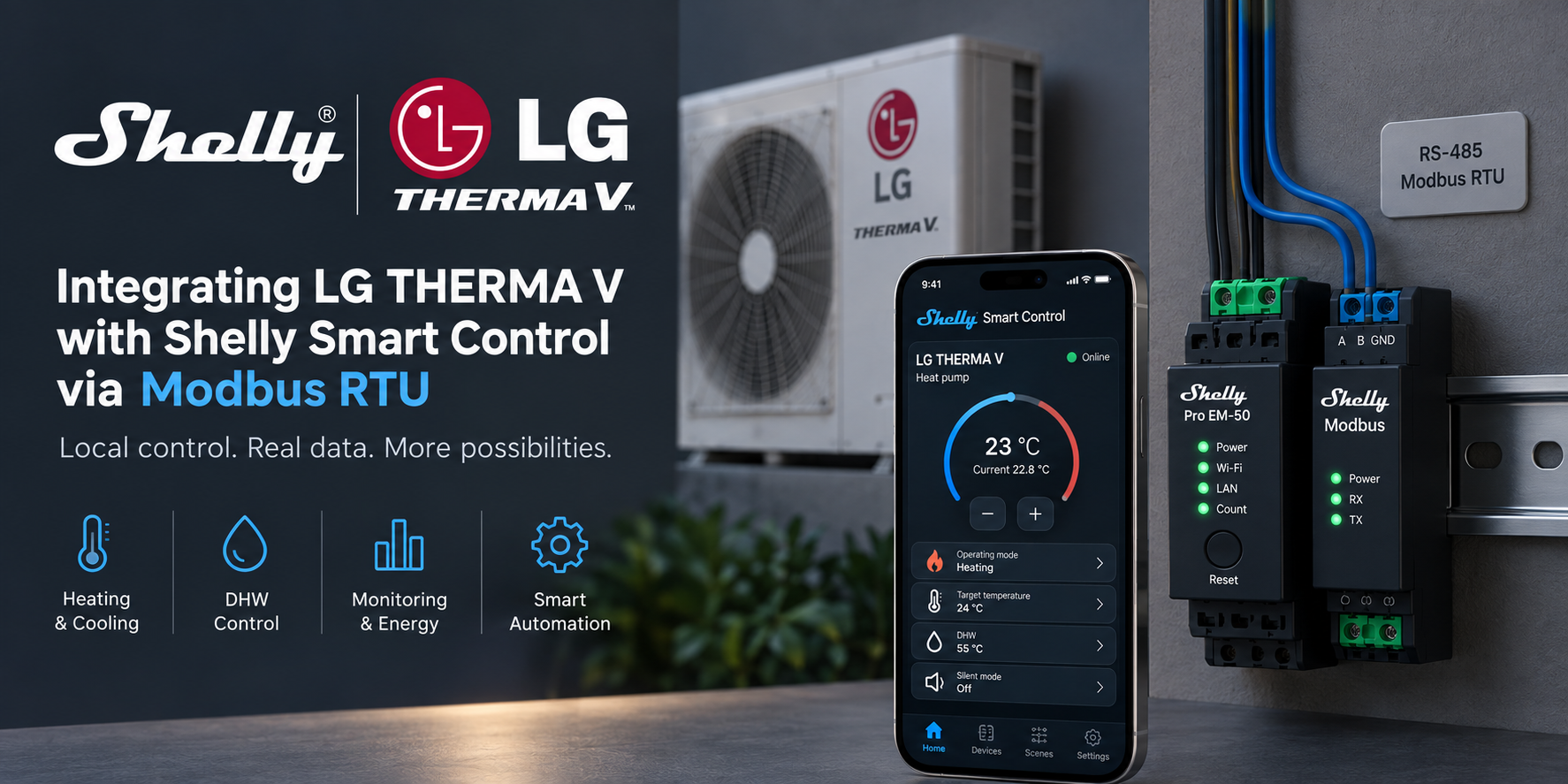
Integrate LG THERMA V directly with the Shelly ecosystem using Modbus RTU. This guide covers RS-485 wiring, Modbus configuration, Virtual Components, local HVAC control, monitoring, and energy measurement through Shelly Smart Control.
Overview
This guide explains how to integrate a compatible LG THERMA V heat pump with Shelly Smart Control using a direct RS-485 / Modbus RTU connection.
The solution uses:
-
Shelly Pro EM-50
-
Shelly Pro Modbus Add-on RS485
-
Shelly Script
-
Shelly Virtual Components
-
Shelly Smart Control
The Shelly device communicates directly with the LG THERMA V over Modbus RTU. No additional gateway, server, or cloud-to-cloud integration is required.
Once configured, the integration provides monitoring and control of:
-
Heat pump power
-
Domestic hot water (DHW)
-
Silent Mode
-
Heating water target temperature
-
DHW target temperature
-
Inlet water temperature
-
Outlet water temperature
-
DHW temperature
-
LG error code
The Shelly Pro EM-50 can also be used to monitor the electrical consumption of the heat pump in the same Shelly installation.
Important
The Modbus register mapping in this guide was validated on a specific LG THERMA V installation. Connector names, Modbus addresses, available registers, and write permissions can differ between THERMA V generations and control boards.
Always verify the service documentation for the exact LG THERMA V model before enabling Modbus writes.
How the integration works
The architecture is fully local:
LG THERMA V
     │
     │ RS-485 / Modbus RTU
     │
     ▼
Shelly Pro Modbus Add-on RS485
     │
     ▼
Shelly Pro EM-50
     │
     ├── Shelly Script
     ├── Virtual Components
     ├── Energy measurement
     │
     ▼
Shelly Smart Control
The Shelly Pro Modbus Add-on operates as a Modbus RTU Client.
The Shelly Script:
-
Configures the serial interface for Modbus RTU Client operation.
-
Connects to the LG THERMA V Modbus server.
-
Reads the physical state of the heat pump.
-
Synchronizes the values with Shelly Virtual Components.
-
Accepts user commands from the Virtual Components.
-
Sends supported commands back to the LG THERMA V.
-
Reads the physical state again to confirm the command.
This provides bidirectional communication between the heat pump and Shelly Smart Control.
Requirements
Hardware
You need:
-
Compatible LG THERMA V with documented Modbus RTU support
-
Shelly Pro EM-50
-
Shelly Pro Modbus Add-on RS485
-
Shielded twisted-pair cable suitable for RS-485
-
Current transformers for the Shelly Pro EM-50 if energy monitoring is required
Software
Use a current Shelly firmware that supports:
-
Shelly Scripts
-
Virtual Components
-
Serial component
-
Modbus RTU Client (
MbRtuClient) -
Shelly Pro Modbus Add-on RS485
For the current Pro Modbus Add-on implementation, use firmware 2.0.0 or later.
RS-485 connection
On the tested LG installation, Modbus communication was available through a connector marked:
CN_COM
This connector designation must not be assumed to be identical on every LG THERMA V model.
Check the service documentation for the exact indoor unit or control PCB before connecting the RS-485 bus.
The basic RS-485 communication pair is:
LG THERMA V              Shelly Pro Modbus Add-on

A / D+        ────────── A
B / D-        ────────── B
If the LG service documentation specifies a communication reference or GND connection, follow that documentation.
For longer RS-485 runs:
-
Use twisted pair for A/B.
-
Keep communication wiring away from high-current cables where possible.
-
Avoid star topology.
-
Terminate the RS-485 bus only where required by the bus topology.
-
Connect the cable shield according to the installation grounding design.
If there is no Modbus communication, one of the first checks should be the A/B polarity.
Modbus configuration
The following settings were used on the tested installation:
|
Parameter |
Value |
|---|---|
|
Protocol |
Modbus RTU |
|
Physical layer |
RS-485 |
|
Baud rate |
9600 |
|
Data bits |
8 |
|
Parity |
None |
|
Stop bits |
1 |
|
Format |
8N1 |
|
LG Modbus server ID |
2 |
|
Shelly Serial / MbRtuClient ID |
100 |
|
Polling interval |
10 seconds |
The script contains these settings in its configuration section:
var CFG = {
  serialId: 100,
  slaveId: 2,
  baud: 9600,
  format: '8N1',
  pollMs: 10000,
  retryMs: 10000,
  gapMs: 100,
  settleMs: 700
};
If the LG THERMA V uses a different Modbus server address, change:
slaveId: 2
to the address configured on the heat pump.
Modbus addressing
The Shelly MbRtuClient API uses zero-based Modbus addresses.
This is important because LG documentation may display registers using conventional Modbus notation such as 40003 or 30003.
For example:
LG documentation        Shelly addr

Coil 00001              0
Holding 40003           2
Input 30003             2
Always verify how the register is represented in the service documentation for the specific LG controller.
Data points used by the integration
The tested integration uses the following LG Modbus points:
|
Function |
Modbus type |
Shelly address |
Scaling |
|---|---|---|---|
|
Power |
Coil |
0 |
Boolean |
|
DHW |
Coil |
1 |
Boolean |
|
Silent Mode |
Coil |
2 |
Boolean |
|
Heating target |
Holding Register |
2 |
signed × 0.1 °C |
|
DHW target |
Holding Register |
8 |
signed × 0.1 °C |
|
Error code |
Input Register |
0 |
Raw value |
|
Inlet temperature |
Input Register |
2 |
signed × 0.1 °C |
|
Outlet temperature |
Input Register |
3 |
signed × 0.1 °C |
|
DHW temperature |
Input Register |
5 |
signed × 0.1 °C |
This table describes the mapping used by this tested solution. It is not intended as a universal LG THERMA V Modbus register map.
Virtual Components
The integration exposes the LG THERMA V in Shelly Smart Control through nine Virtual Components.
|
Virtual Component |
Name |
Function |
|---|---|---|
|
|
LG Power |
Heat pump enable / disable |
|
|
LG DHW |
DHW enable / disable |
|
|
LG Silent Mode |
Silent Mode enable / disable |
|
|
LG Heating Target |
Heating water temperature target |
|
|
LG DHW Target |
DHW temperature target |
|
|
LG Inlet Temperature |
Current inlet water temperature |
|
|
LG Outlet Temperature |
Current outlet water temperature |
|
|
LG DHW Temperature |
Current DHW temperature |
|
|
LG Error Code |
Current LG error code |
number:208 is intentionally unused in the current implementation.
Heating controls
The following components can be used together for heating:
LG Power
LG Heating Target
LG Outlet Temperature
This provides:
-
Heating enable/disable
-
Current outlet water temperature
-
Heating water temperature setpoint
Domestic hot water controls
The following components can be used together for DHW:
LG DHW
LG DHW Target
LG DHW Temperature
This provides:
-
DHW enable/disable
-
Current tank temperature
-
DHW temperature setpoint
Installing the Shelly Script
Open the Shelly device and go to:
Scripts → Create script
Create a new script, for example:
LG THERMA V
Paste the provided script: https://github.com/ALLTERCO/shelly-script-examples/tree/main/modbus/LG
lg-therma-v-pro-em50_vc.shelly.js
Before starting it, verify the configuration:
var CFG = {
  serialId: 100,
  slaveId: 2,
  baud: 9600,
  format: '8N1',
  pollMs: 10000,
  retryMs: 10000,
  gapMs: 100,
  settleMs: 700
};
Then:
-
Save the script.
-
Enable Run on startup.
-
Start the script.
-
Open the script logs.
First startup
The integration intentionally uses a read-before-write startup sequence.
This prevents a stale value in Shelly Smart Control from being written immediately to the heat pump when the script starts.
The startup sequence is:
Start script
    ↓
Check Virtual Components
    ↓
Configure RS-485
    ↓
Connect to LG
    ↓
Read actual LG state
    ↓
Update Virtual Components
    ↓
Enable commands
Commands remain blocked until the initial synchronization has completed successfully.
A successful startup should produce a log similar to:
[LG] READY: 9/9 synchronized. Commands enabled.
At this point the Shelly controls represent the physical state reported by the LG THERMA V.
Command verification
When a supported value is changed from Shelly Smart Control, the integration does not assume that the command was accepted.
The sequence is:
User changes value
      ↓
Shelly sends Modbus write
      ↓
LG processes command
      ↓
Shelly reads LG again
      ↓
Virtual Component is updated
The value presented in Shelly Smart Control therefore follows the state read back from the LG controller.
This is particularly important for HVAC equipment because the controller may reject or modify a command depending on:
-
Operating mode
-
Current system state
-
Temperature limits
-
Active protection
-
LG control logic
The integration does not bypass the internal protection or safety logic of the heat pump.
Communication fault handling
If Modbus communication is lost, the script:
-
Marks the integration as not ready.
-
Blocks new writes.
-
Stops treating the current Virtual Component values as authoritative.
-
Attempts to reconnect.
-
Reads the physical LG state again.
-
Re-enables commands only after successful synchronization.
A communication problem may produce a message similar to:
[LG] PAUSED: ...
Writes blocked; retrying.
This prevents queued or stale commands from being blindly sent after communication is restored.
Shelly Smart Control
After successful synchronization, the nine Virtual Components are available in the Shelly ecosystem.
They can be used for:
-
Direct heat-pump control
-
Temperature monitoring
-
DHW control
-
Silent Mode
-
Error monitoring
-
Dashboards
-
Scenes
-
Automations
The Shelly Pro EM-50 can additionally provide electrical measurements for the heat pump, allowing operating data and energy consumption to be monitored within the same Shelly installation.
Troubleshooting
No communication with the LG THERMA V
Check:
-
A/B wiring
-
Modbus server address
-
Baud rate
-
Serial format
-
LG Modbus configuration
-
Correct communication connector
-
RS-485 termination
-
Cable topology
Tested settings are:
9600 baud
8N1
Server ID 2
These values are not guaranteed to apply to every LG THERMA V.
RX/TX activity but no valid response
Verify the RS-485 A/B polarity.
Also verify that no other Modbus client is attempting to control the same RS-485 bus simultaneously.
Temperatures are incorrect
The tested temperature registers use:
signed 16-bit value × 0.1 °C
For example:
350 → 35.0 °C
Negative values are represented using a signed 16-bit Modbus value.
Reading works but control does not
Check that:
-
The selected register is writable on the exact LG model.
-
The heat pump allows external control.
-
The requested value is inside the valid LG range.
-
The initial synchronization completed successfully.
-
The script reports that commands are enabled.
A readable Modbus register is not necessarily writable.
The integration stays in PAUSED state
Check the Shelly Script logs.
The script intentionally keeps writes disabled if:
-
A required Virtual Component is unavailable.
-
The serial interface cannot be configured.
-
Modbus communication fails.
-
A received value is outside the expected range.
-
The initial physical state cannot be established.
Resolve the communication problem before attempting control.
Safety and limitations
This integration communicates with the LG controller through its digital communication interface. It does not replace or bypass:
-
LG safety controls
-
Compressor protection
-
Temperature protection
-
Flow protection
-
Installer configuration
-
Electrical protection
Before enabling writes:
-
Confirm Modbus support for the exact LG THERMA V model.
-
Confirm the correct communication connector.
-
Confirm the Modbus server address.
-
Confirm the register map.
-
Confirm which registers are writable.
-
Confirm the permitted value ranges.
Do not assume that register addresses from one LG THERMA V generation are valid for another.
Result
After completing the integration, the LG THERMA V can be monitored and controlled directly from the Shelly ecosystem through a local RS-485 Modbus RTU connection.
The final architecture remains simple:
LG THERMA V
      ↕
Modbus RTU / RS-485
      ↕
Shelly Pro Modbus Add-on
      ↕
Shelly Pro EM-50
      ↕
Shelly Smart Control
No external automation server is required for the integration to operate.
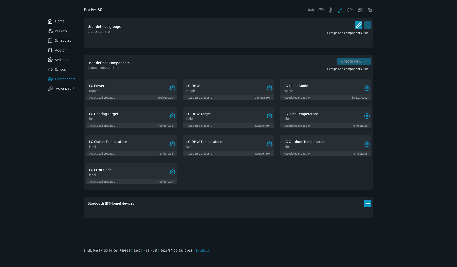
Virtual Components created on the Shelly device
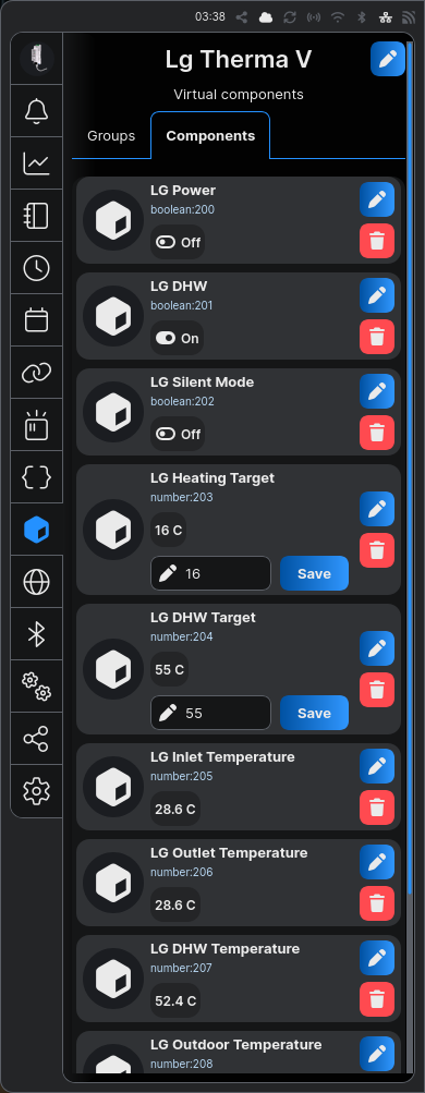
LG THERMA V Virtual Components in the Shelly device interface
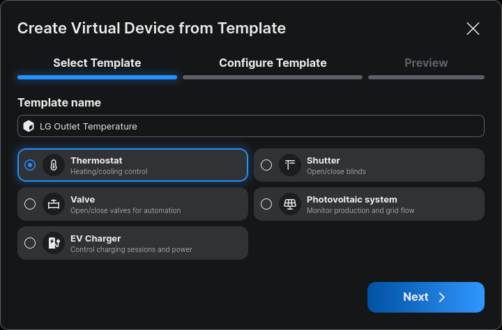
Creating a thermostat Virtual Device from a template
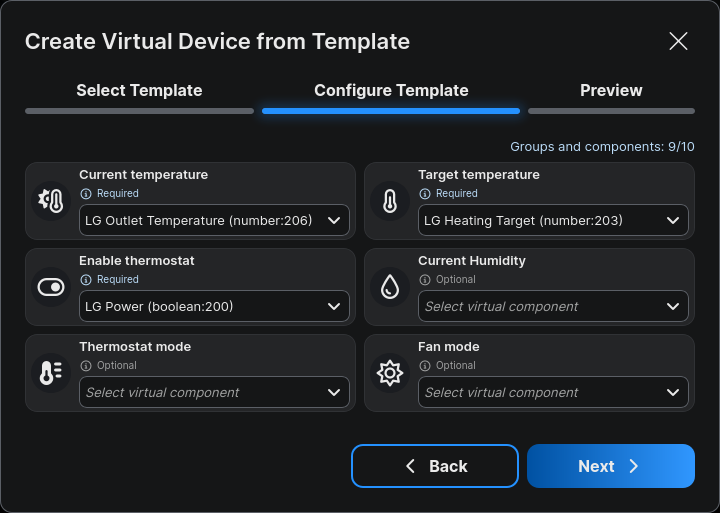
Assigning LG THERMA V components to the thermostat template
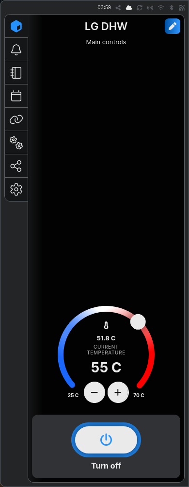
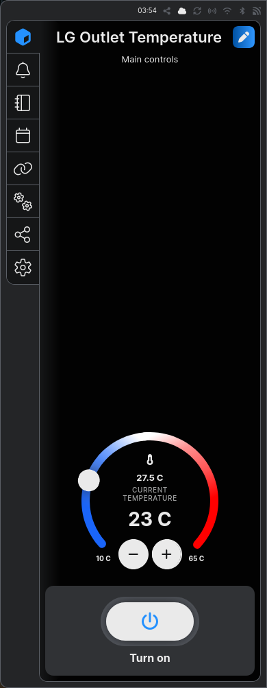
The Shelly ecosystem now supports direct integration with LG THERMA V through Modbus RTU.
Its main operating values and controls are exposed as Shelly Virtual Components and combined into a thermostat-style Virtual Device.
The solution allows local control of heating, DHW, target temperatures, Silent Mode, temperature monitoring, error status, and energy consumption.
It can be used in residential homes, offices, hotels, schools, technical rooms, and other buildings with compatible LG THERMA V systems.
The same approach can also be adapted to other Modbus RTU-compatible HVAC equipment, creating fully local HVAC integrations inside Shelly Smart Control.