
Automation as an Electrical System, Not an Add-On
When discussing building automation - whether for apartments, hotels, or offices - the most important shift is conceptual: automation must be treated as a core electrical system, not as a later digital overlay. In practice, a standardized automation baseline always includes three actively controlled subsystems: lighting, HVAC, and window blinds. In parallel, several parameters must be continuously monitored: illumination levels, room temperature, perimeter state of doors and windows, and consumption of electricity and water.
What unifies these systems is not user interface or software, but electrical topology. By designing these subsystems before construction begins, it becomes possible to optimize energy flows, maintenance effort, and long-term operational costs. This early integration is what enables predictable behavior and scalability. The automation system is no longer reactive; it becomes part of the building’s infrastructure.
The size of an apartment or unit naturally affects the number of circuits and devices, but the underlying cabinet structure and control logic remain consistent. Scalability is achieved not through redesign, but through modular expansion within the same electrical concept.
The Electrical Cabinet as the Automation Core
At the heart of standardized automation lies the electrical cabinet. This cabinet is not merely a distribution board; it is a control and monitoring node designed with strict safety, serviceability, and documentation principles.
Every cabinet begins with two non-automated protection layers:
-
Circuit breakers (CB)
-
Residual current breakers (RCB)
These devices operate independently of any control logic and form the immutable safety foundation of the system. Immediately downstream of the main circuit breaker sits the main energy meter, responsible for measuring total consumption of the apartment, office unit, or hotel room.
From there, loads are divided into logical groups. Each group is protected by its own RCB and sub-CBs, allowing selective isolation and fault containment. Before certain groups - typically those subject to automation or energy management - automated contact systems are introduced. These allow entire load groups to be powered down or restored based on operational state, such as holiday mode or office vacancy.
All control devices - relays, dimmers, RGBW controllers - are DIN-mounted within the cabinet. Wall switches, lighting circuits, blind motors, and socket groups are all wired directly back to the cabinet and terminated on dedicated terminal blocks. This approach eliminates distributed logic points and ensures that all signal paths remain accessible and documented.
Importantly, the system does not rely on a centralized hub. Devices operate autonomously, forming a distributed intelligence model where failure of one component does not collapse the entire system.
Manual Mode and Serviceability
A critical requirement of any automation system is the ability to revert to manual operation. In this architecture, manual mode is implemented not through additional selector switches - which add cost and complexity - but through terminal-based bypassing.
Because all loads and control lines terminate in the cabinet, automation devices can be bypassed simply by re-terminating conductors on predefined terminal points. This design assumes that cabinet access is restricted to certified personnel. Maintenance staff are trained to work within this framework, and all conductors are labeled according to IEC 81346, ensuring clarity even years after installation.
Critical loads - such as refrigerators, boilers, or essential lighting - are always placed on dedicated circuits. These remain functional regardless of automation state, guaranteeing safety and usability during maintenance or fault conditions.
Lighting Control Architecture
Lighting is treated as a structured subsystem rather than a collection of individual fixtures. In a standardized apartment, lighting design follows zoning rules:
-
Corridors and closets use simple on/off control.
-
Living rooms and kitchens use dimmable lighting and LED strips.
-
Bedrooms emphasize ambient lighting combined with indirect LED sources.
Wall interfaces may use momentary switches or traditional buttons, depending on client preference and interior design requirements. Electrically, both options are equivalent because switches carry only control signals, not load current.
All lighting circuits terminate in the cabinet. Configuration - such as switch behavior, dimming curves, and grouping - is performed locally at device level. This allows late-stage changes without rewiring. For electricians, this simplifies installation. For system integrators, it enables deterministic logic. For interior designers, it allows fixture layouts to evolve without structural changes.
Scenes and groups can be implemented locally within devices, ensuring that basic operation remains available even if network connectivity is lost.
Curtain and Blinds Control
Curtain and blinds automation is treated as an optional subsystem, defined during the design phase in coordination with the client. Most installations use low-power controllers supplied either by nearby wall adapters or by a centralized cabinet power supply.
Interlocking between up and down motion is handled during device calibration. Safety features - such as end-stop detection and position limits - are implemented at device level. Wall controls are minimal; most user interactions are handled via scenes rather than direct motor commands.
Where cabinet-based power supplies are used, cable lengths are kept short to minimize voltage drop. This ensures reliable operation while maintaining serviceability.
Low-Voltage Power Distribution
Low-voltage distribution follows pragmatic rules:
-
5 V devices use USB-based power delivery.
-
12 V and 24 V supplies are kept local, with cable runs typically under 5 m.
-
Long low-voltage runs are avoided due to impedance and loss considerations.
Protection is always two-stage: CB and RCB on the mains side, followed by current protection on the secondary side of the power supply. Standard, replaceable power supplies are preferred to reduce downtime and simplify maintenance.
Power Consumption Measurement and Automation
Energy measurement uses a hybrid approach. In addition to a main apartment meter, most control devices provide per-group or per-circuit metering. This layered visibility allows abnormal behavior to be detected early and enables detailed analysis of consumption patterns.
All load groups are considered relevant. In modern buildings - especially those with local energy production - every kilowatt matters. By modeling consumption behavior, the system can automate power flows rather than simply record them.
This data forms the basis for optimization logic, advisory systems, and load scheduling. Certified devices ensure that measurements are reliable and suitable for decision-making.
Load Prioritization and Peak Management
Automation of power flows begins with prioritization. High-consumption loads such as cookers, boilers, EV chargers, HVAC systems, and refrigeration are modeled individually. By scheduling these loads and applying sequencing logic, peak demand can be reduced without compromising usability.
When applied across multiple apartments or rooms, this approach smooths the load curve of the entire building. At scale, the same logic can be extended to neighborhoods or districts, contributing to grid stability and infrastructure longevity.
Holiday Mode as a Safety Function
Holiday mode is primarily a safety and energy management function. When activated, non-critical circuits are disconnected via automated contactors. Critical loads remain powered on separate circuits.
Automation remains partially active: presence simulation, baseline heating or cooling, and scheduled pre-conditioning before return are all possible. The system itself does not replace a security installation but can forward relevant events to external security systems.
Security Monitoring via Wireless Sensors
Security monitoring relies on a combination of wireless sensors: presence detectors, radar sensors, door and window contacts, distance sensors, and manual inputs. These devices are battery powered, with typical replacement cycles of approximately 2.5 years.
Sensors communicate via low-power Bluetooth using the BTHome protocol. Nearby automation devices act as gateways, and redundancy is achieved by deploying multiple gateways per zone. Sensors report battery status and operational health, allowing maintenance to be scheduled predictively.
Events are multi-dimensional. A single door sensor may report contact state, tilt, illumination, and battery level, each capable of triggering distinct automation actions.
HVAC Integration Boundary
HVAC automation respects a strict boundary of responsibility. Actuators - such as thermostats, TRV heads, and relays - interface with heating, cooling, and ventilation systems. Temperature and environmental data is collected via dedicated sensors.
All device-specific safety logic remains within the HVAC vendor’s controller. The automation system provides enable signals, setpoints, and monitoring, but does not override protective mechanisms such as compressor lockout or minimum cycle times.
During holiday mode, HVAC is treated as a critical but reduced-priority load, maintaining safe baseline conditions rather than full comfort.
Cabinet Layout and Documentation
Cabinets are typically laid out horizontally. The first DIN rail row is reserved for terminal blocks, simplifying wiring and future modifications. Subsequent rows contain protection devices and control modules.
Neutrals and protective earth conductors are handled via terminal blocks rather than traditional busbars, reflecting the cabinet’s hybrid role between distribution and control. All cabinets include local documentation, diagrams, and QR codes linking to digital records. This ensures continuity even if physical documentation is lost.
Network and Commissioning Baseline
Network configuration follows strict rules. Devices initially receive addresses via DHCP, after which static reservations are assigned. No unmanaged DHCP clients remain after commissioning. Device identification is assisted via mDNS during provisioning.
Time synchronization relies on NTP. In isolated networks, a local NTP server is mandatory. Firmware is updated before any load is energized. Only after software validation are electrical tests performed and approved.
Scalability and Upgradeability
Standardization enables repetition. Power measurement concepts, safety architecture, device grouping, and BOM remain identical across similar units. This dramatically reduces errors and commissioning time in multi-unit projects such as hotels or apartment buildings.
Upgrade paths are built into the electrical design. Zones with minimal equipment can later be expanded using modular devices without reworking the installation. This ensures long-term adaptability without sunk costs.
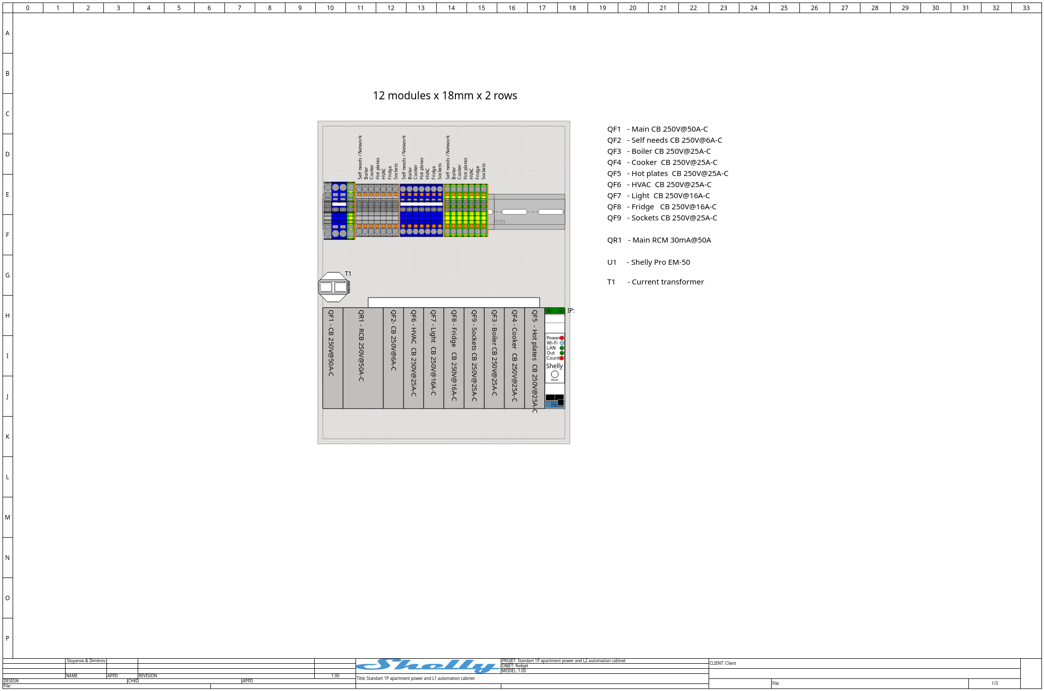
Level 1:
-
QF1 - Main CB 250V@50A-C
-
QF2 - Self needs CB 250V@6A-C
-
QF3 - Boiler CB 250V@25A-C
-
QF4 - Cooker CB 250V@25A-C
-
QF5 - Hot plates CB 250V@25A-C
-
QF6 - HVAC CB 250V@25A-C
-
QF7 - Light CB 250V@16A-C
-
QF8 - Fridge CB 250V@16A-C
-
QF9 - Sockets CB 250V@25A-C
-
QR1 - Main RCM 30mA@50A
-
U1 - Shelly Pro EM-50
-
T1 - Current transformer
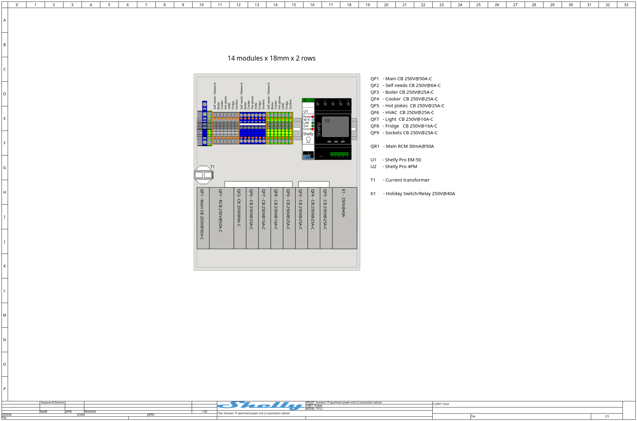
Level 2:
-
QF1 - Main CB 250V@50A-C
-
QF2 - Self needs CB 250V@6A-C
-
QF3 - Boiler CB 250V@25A-C
-
QF4 - Cooker CB 250V@25A-C
-
QF5 - Hot plates CB 250V@25A-C
-
QF6 - HVAC CB 250V@25A-C
-
QF7 - Light CB 250V@16A-C
-
QF8 - Fridge CB 250V@16A-C
-
QF9 - Sockets CB 250V@25A-C
-
QR1 - Main RCM 30mA@50A
-
U1 - Shelly Pro EM-50
-
U2 - Shelly Pro 4PM
-
T1 - Current transformer
-
K1 - Holiday Switch/Relay 250V@40A
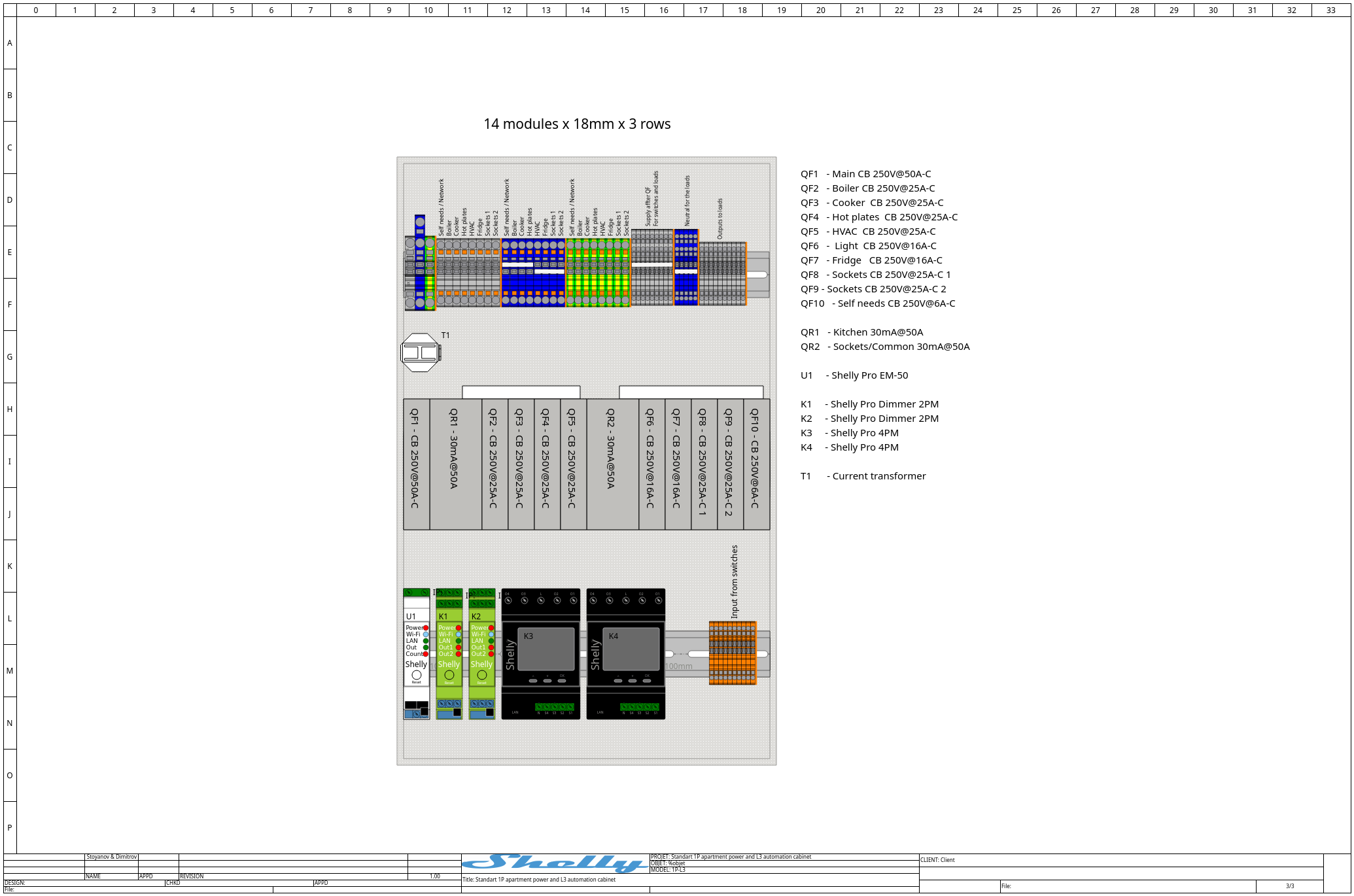
Level 3
-
QF1 - Main CB 250V@50A-C
-
QF2 - Boiler CB 250V@25A-C
-
QF3 - Cooker CB 250V@25A-C
-
QF4 - Hot plates CB 250V@25A-C
-
QF5 - HVAC CB 250V@25A-C
-
QF6 - Light CB 250V@16A-C
-
QF7 - Fridge CB 250V@16A-C
-
QF8 - Sockets CB 250V@25A-C 1
-
QF9 - Sockets CB 250V@25A-C 2
-
QF10 - Self needs CB 250V@6A-C
-
QR1 - Kitchen 30mA@50A
-
QR2 - Sockets/Common 30mA@50A
-
U1 - Shelly Pro EM-50
-
K1 - Shelly Pro Dimmer 2PM
-
K2 - Shelly Pro Dimmer 2PM
-
K3 - Shelly Pro 4PM
-
K4 - Shelly Pro 4PM
-
T1 - Current transformer
Conclusion
Standardized apartment automation is not defined by apps or user interfaces, but by electrical discipline. By placing automation logic inside a well-designed cabinet, separating safety from control, and treating monitoring as a first-class function, buildings become more efficient, maintainable, and resilient.
In this context, platforms such as Shelly provide the technical building blocks - not as a marketing layer, but as components in a structured electrical system.