This article provides information on how to connect Deye solar inverter with Shelly Pro MODBUS Add-on over RS485 communication interface.
Introduction
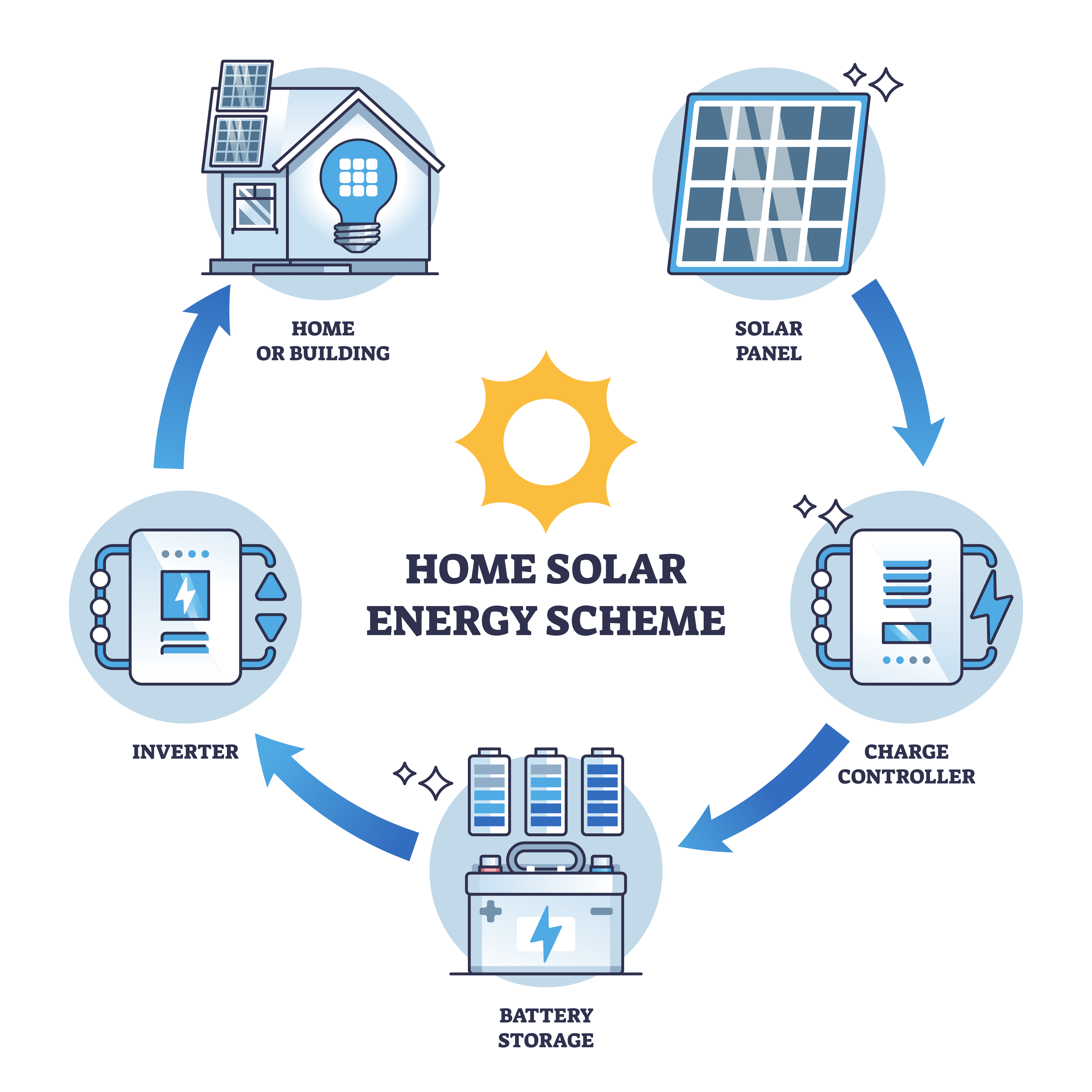
Modern households increasingly rely on renewable energy solutions to reduce expenses, increase energy autonomy, and participate in smart-grid optimization. This project presents a fully integrated solar energy system composed of a Deye inverter, an external battery, solar panels, an electrical distribution box with an ATS (Automatic Transfer Switch), and a Shelly Pro monitoring network featuring the Shelly Pro EM-50 and RS485 Add-on.
The system provides continuous monitoring of energy production, consumption, and storage, enabling informed decisions related to energy cost optimization, self-consumption, and load control. Additionally, by leveraging battery storage and intelligent algorithms, the system can sell energy back to the grid when electricity prices are high and store energy when prices are low.
System Architecture
The core system consists of:
-
Deye single-phase inverter with PV input, battery storage support
-
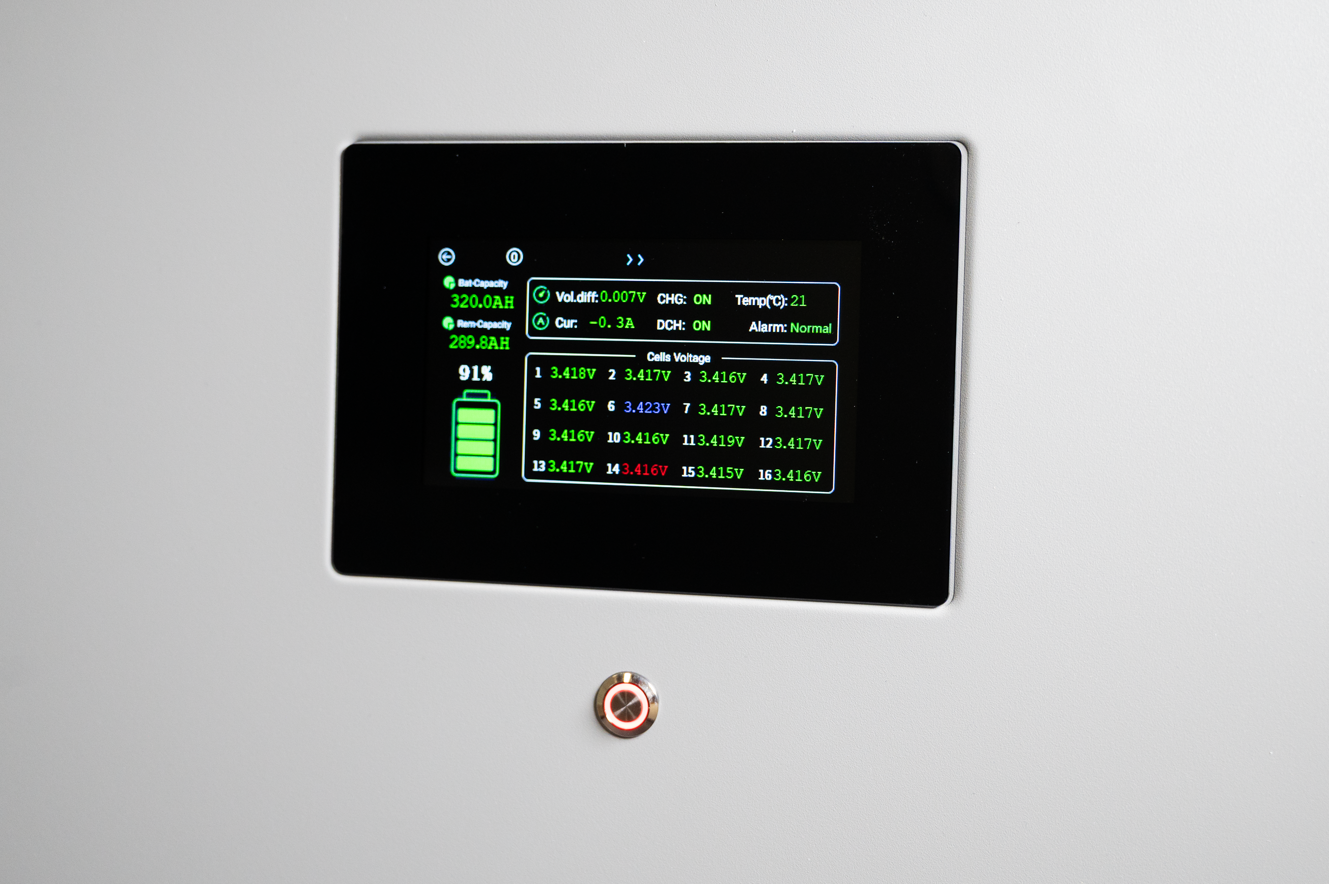
External Li-ion battery bank with JK-BMS 200
-
PV array of solar panels
-
ATS-enabled electrical distribution cabinet
-
Shelly Pro EM-50 energy meter
-
Shelly Pro RS485 Add-on
-
Communication wiring (power and data)
This architecture allows seamless energy flow between the PV array, inverter, household loads, battery storage, and the grid. The ATS ensures automatic transfer of power in the event of grid failure, maintaining power continuity.
Hardware Integration
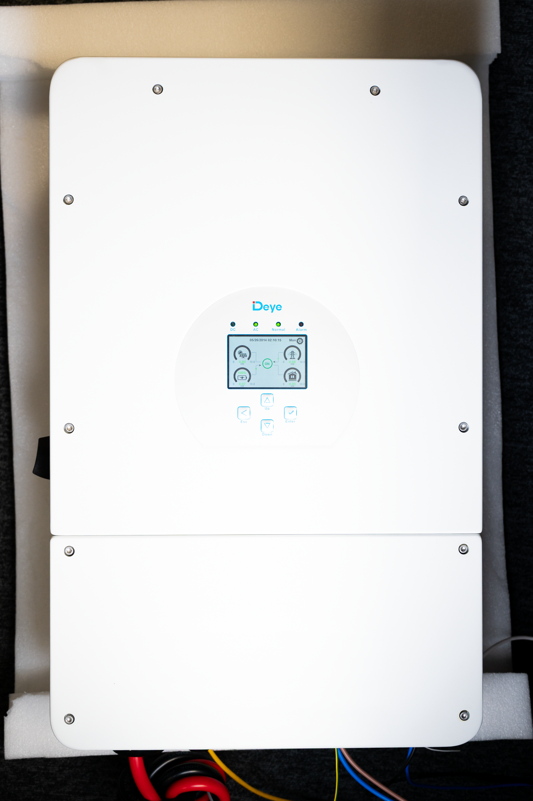
1. Deye Inverter Installation and Configuration
The Deye inverter serves as the central control device. It performs PV energy management using MPPT controler, AC coupling, DC battery management, and grid synchronization. Proper commissioning includes configuring inverter modes (self-consumption, grid sell, time-of-use), setting charge/discharge limits, and defining battery compatibility parameters.
2. Battery System Configuration
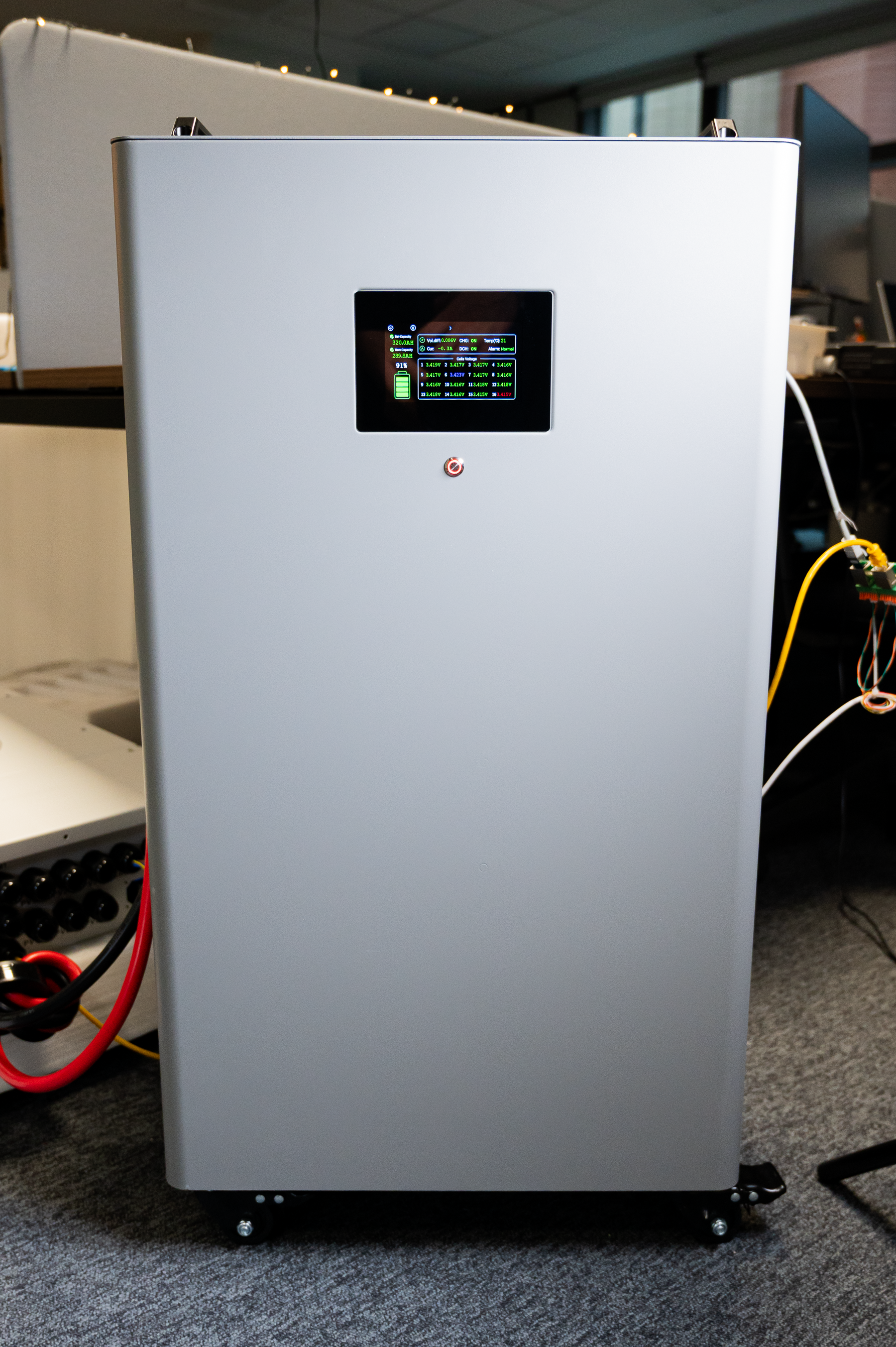
The external battery is integrated via CAN/RS485 communication to establish synchronized charging behavior with the inverter. Configuration steps include:
-
Voltage and current limits
-
Battery chemistry settings
-
Charge/discharge timing
-
Grid export permissions
Correct configuration ensures the battery will store energy when electricity cost is low and discharge when profitable.
3. Solar Panel Integration
Solar panels are wired using appropriate DC cabling, surge protection, and connected to the inverter PV inputs. Sizing considerations include energy demand, seasonal performance, and local regulations.
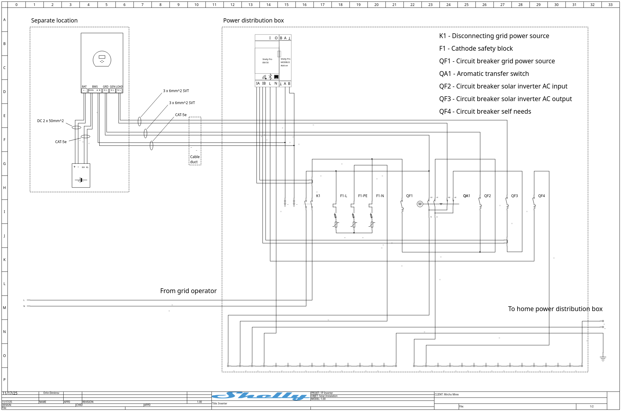
4. Electrical Distribution Cabinet with ATS
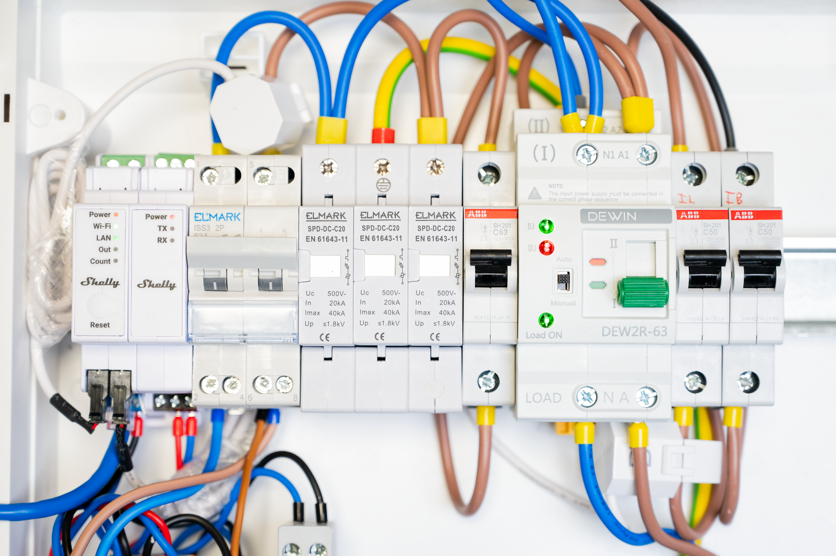
The ATS integrates grid supply, inverter AC output, and household load distribution. It automatically switches to inverter power during grid outage, protecting electronics and maintaining operational continuity.
There are other ways an inverter to be integrated into a house electricity distribution. This design was chosen as to allow maximum flexibility for maintenance of the system and was targeting an off-grid with occasional on-grid without selling to the grid scenario.
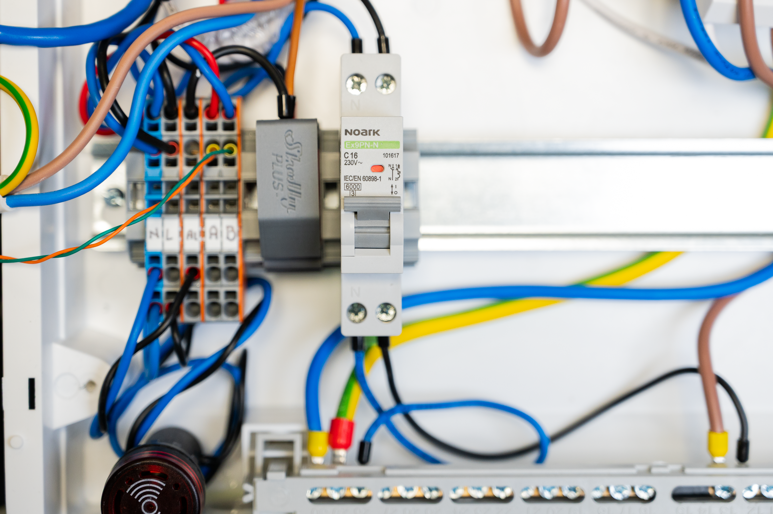
Data Acquisition and Cloud Communication
The Shelly Pro EM-50 provides granular measurements of energy flow across single or multiple phases. With the RS485 Add-on, Modbus-RTU communication can be established for data acquisition.
Cloud integration allows for:
-
Real-time remote monitoring
-
Visualization dashboards
-
Notification workflows
-
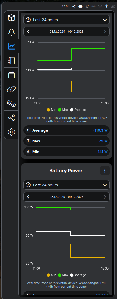
Historical data logging
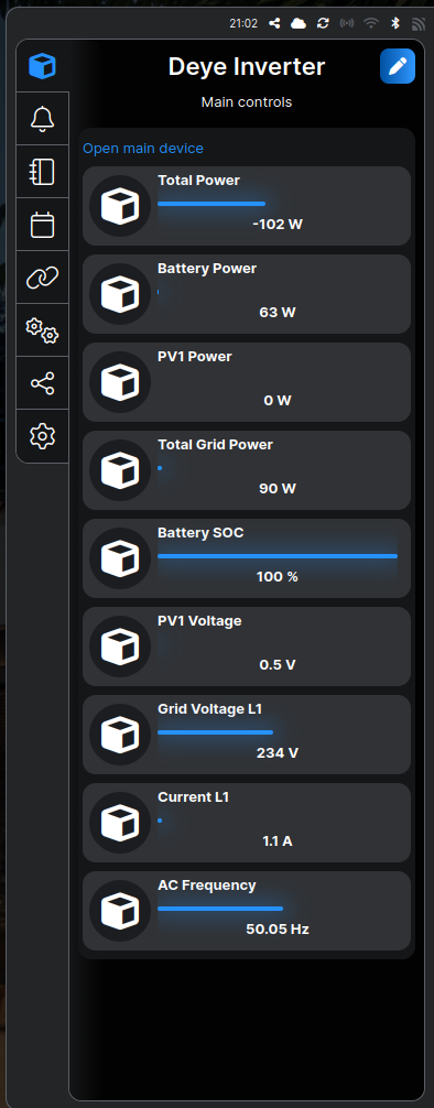
Virtual Component Dashboard
For displaying the data retrieved from the inverter a built in system for extending Shelly devices is user - virtual components.
The system produces nine key parameters useful for both monitoring and decision-making:
-
Solar generation power
-
Household consumption
-
Grid import
-
Grid export
-
Battery charge level
-
Battery charge/discharge rate
-
Inverter efficiency
-
PV voltage/current
-
Cost per kWh (dynamic)
These values are visualized within a unified dashboard for daily operations.
Data Acquisition Script via Modbus-RTU
The Shelly Pro RS485 Add-on streams data from the inverter/battery using the Modbus-RTU protocol. A custom script polls the device at defined intervals and publishes results to the cloud.
Script responsibilities include:
-
Register mapping
-
Value parsing and scaling
-
Error handling
-
Data caching and pushing to cloud storage
This script enables real-time feedback loops for load-control automation.
Embedded Data Acquisition Script
The system relies on an embedded JavaScript application running on the Shelly Pro platform to communicate with the inverter and collect performance data in real time. The script retrieves values from Modbus registers, scales them appropriately, and publishes them as virtual components, enabling dashboards and automatons to consume structured information.
Disclaimer the script it tested and works properly on 1.8.99-dev148102 firmware revision.
/*
  Shelly Europe Ltd. - Integrations Team


  This example is dedicated for communication over MODBUS-RTU with a Deye solar inverter.
  ENTITIES-based version + Virtual Components.
*/

const INVERTER_MODBUS_SERVER_ID = 1;

// Get a MODBUS-RTU endpoint: ID 1, baud rate 9600, 8 data bits, No parity, 1 stop bit.
const MODBUS_ENDPOINT = ModbusController.get(INVERTER_MODBUS_SERVER_ID, {
   baud: 9600,
   mode: "8N1",
   pause_ms: 2000
});

// ENTITIES table describing all parameters + mapping to virtual components
const ENTITIES = [{
      name: "Total Power",
      units: "W",
      reg: {
         addr: 175,
         rtype: ModbusController.REGTYPE_HOLDING,
         itype: "i16",
         bo: ModbusController.BE,
         wo: ModbusController.BE
      },
      scale: 1,
      rights: "R",
      vcId: "number:200",
      handle: null,
      vcHandle: null
   },
   {
      name: "Battery Power",
      units: "W",
      reg: {
         addr: 190,
         rtype: ModbusController.REGTYPE_HOLDING,
         itype: "i16",
         bo: ModbusController.BE,
         wo: ModbusController.BE
      },
      scale: 1,
      rights: "R",
      vcId: "number:201",
      handle: null,
      vcHandle: null
   },
   {
      name: "PV1 Power",
      units: "W",
      reg: {
         addr: 186,
         rtype: ModbusController.REGTYPE_HOLDING,
         itype: "u16",
         bo: ModbusController.BE,
         wo: ModbusController.BE
      },
      scale: 1,
      rights: "R",
      vcId: "number:202",
      handle: null,
      vcHandle: null
   },
   {
      name: "Total Grid Power",
      units: "W",
      reg: {
         addr: 169,
         rtype: ModbusController.REGTYPE_HOLDING,
         itype: "i16",
         bo: ModbusController.BE,
         wo: ModbusController.BE
      },
      scale: 10,
      rights: "R",
      vcId: "number:203",
      handle: null,
      vcHandle: null
   },
   {
      name: "Battery SOC",
      units: "%",
      reg: {
         addr: 184,
         rtype: ModbusController.REGTYPE_HOLDING,
         itype: "u16",
         bo: ModbusController.BE,
         wo: ModbusController.BE,
         poll_int: 10000
      },
      scale: 1,
      rights: "R",
      vcId: "number:204",
      handle: null,
      vcHandle: null
   },
   {
      name: "PV1 Voltage",
      units: "V",
      reg: {
         addr: 109,
         rtype: ModbusController.REGTYPE_HOLDING,
         itype: "u16",
         bo: ModbusController.BE,
         wo: ModbusController.BE
      },
      scale: 0.1,
      rights: "R",
      vcId: "number:205",
      handle: null,
      vcHandle: null
   },
   {
      name: "Grid Voltage L1",
      units: "V",
      reg: {
         addr: 150,
         rtype: ModbusController.REGTYPE_HOLDING,
         itype: "u16",
         bo: ModbusController.BE,
         wo: ModbusController.BE,
         poll_int: 10000
      },
      scale: 0.1,
      rights: "R",
      vcId: "number:206",
      handle: null,
      vcHandle: null
   },
   {
      name: "Current L1",
      units: "A",
      reg: {
         addr: 164,
         rtype: ModbusController.REGTYPE_HOLDING,
         itype: "i16",
         bo: ModbusController.BE,
         wo: ModbusController.BE
      },
      scale: 0.01,
      rights: "R",
      vcId: "number:207",
      handle: null,
      vcHandle: null
   },
   {
      name: "AC Frequency",
      units: "Hz",
      reg: {
         addr: 192,
         rtype: ModbusController.REGTYPE_HOLDING,
         itype: "u16",
         bo: ModbusController.BE,
         wo: ModbusController.BE,
         poll_int: 10000
      },
      scale: 0.01,
      rights: "R",
      vcId: "number:208",
      handle: null,
      vcHandle: null
   },
];

function getScaledValue(ent) {
   return ent.handle.getValue() * ent.scale;
}

function updateVc(ent) {
   if (!ent.vcHandle) return;
   const new_val = getScaledValue(ent);
   const old_val = ent.vcHandle.getValue();
   console.log(ent.name + ": " + old_val + " -> " + new_val + " [" + ent.units + "]");
   ent.vcHandle.setValue(new_val);
   return old_val;
}


function init() {
   for (let i = 0; i < ENTITIES.length; i++) {
      let ent = ENTITIES[i];
      ent.handle = MODBUS_ENDPOINT.addEntity(ent.reg);
      if (ent.vcId) {
         ent.vcHandle = Virtual.getHandle(ent.vcId);
         ent.handle.on("change", function (handle) {
            updateVc(ent);
         });
      }
   }


   Timer.set(10000, false, function () {
      for (let i = 0; i < ENTITIES.length; i++) {
         updateVc(ENTITIES[i]);
      }
   });
}


// Run the application.
init();
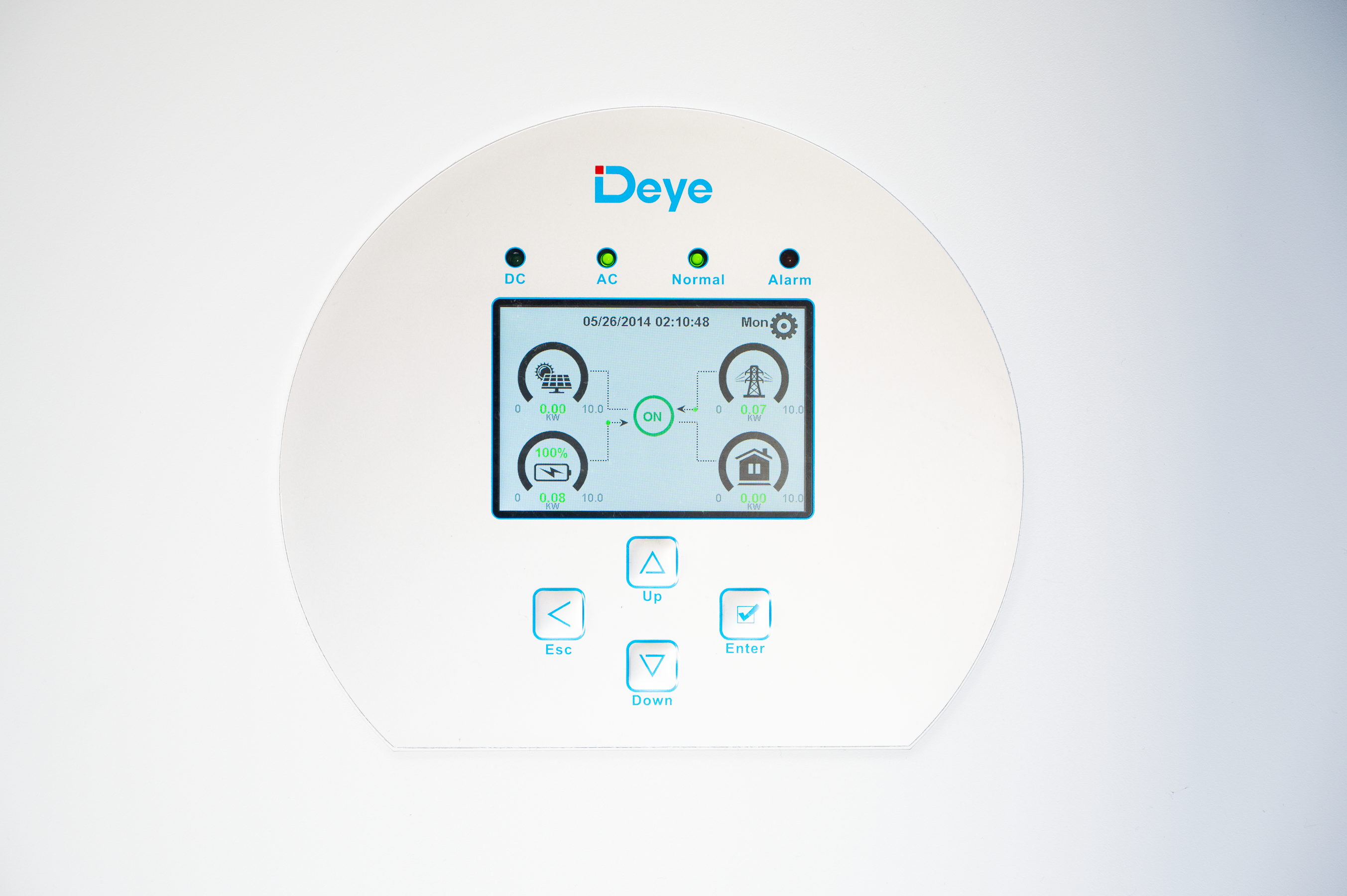
The result of acquisition results can be seen on the following screenshot.
Energy Management Strategies
1. Storing Energy When the Price is Low
Time-of-use pricing enables strategic battery charging during off-peak energy cost windows. The system synchronizes with pricing data and schedules battery charge operations accordingly.
2. Selling Energy Back to the Grid at Peak Price
When energy prices spike, and battery storage is sufficient, the system exports energy back to the grid. This is controlled by inverter configuration and automated decision-making rules.
3. Determining Best Time to Charge EV
EV charging can be optimized using solar surplus or cheap night-time grid electricity. Decision factors include:
-
Real-time production/consumption
-
Battery state of charge
-
Grid pricing
-
Planned EV usage
Automation engine can switch charging sources or postpone charging based on cost-benefit logic.
Use Case: Household Energy Balancing
A typical daily workflow:
-
Morning: Solar energy powers household loads; surplus begins charging battery
-
Afternoon: Excess power charges battery fully and exports to grid
-
Evening: Battery discharges to reduce grid imports at higher cost
-
Night: Battery charges from grid if night electricity is cheaper
-
Anytime: EV charging scheduled only when cost-efficient
Benefits
-
Reduced electricity cost
-
Revenue from grid export
-
Improved resilience and autonomy
-
Sustainable and transparent energy consumption
-
Scalable for future devices and smart home integration
Conclusion
This project demonstrates how to combine commercially available hardware and open-source tools to create a powerful energy optimization system. With real-time monitoring, automated decision-making, and intelligent storage management, households can actively participate in modern energy ecosystems while minimizing costs and maximizing sustainability.