
A Shelly-based automatic transfer switch cabinet selects between grid and backup supply, keeps the preferred source visible, and uses interlocked contactors so a home or small site can move between sources without manual switching.
Grid outages create a different problem than simple load shedding. The site needs a clear decision about which source is allowed to feed the load: grid, backup, or none. The control must be easy to explain, electrically interlocked, and visible enough for an installer or customer to trust the behavior.
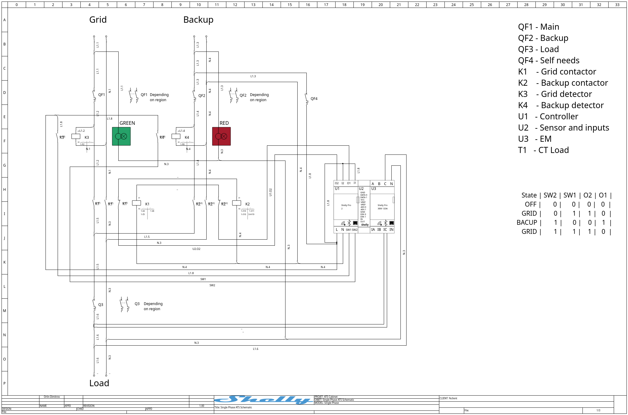
This use case demonstrates a Shelly-controlled single-phase automatic transfer switch. The cabinet detects grid and backup availability, uses a Shelly Pro 2 as the controller, and drives separate contactors for grid and backup. When both sources are available, the cabinet gives priority to the grid.
Regional Wiring Context
Single-phase ATS design is especially relevant in markets where 1P residential installations dominate. Other regions need the same source-selection logic adapted to 2P or mixed-service installations.
|
Continent |
1P Dominant |
2P Dominant |
Mixed |
|---|---|---|---|
|
Europe |
~85% |
~15% |
- |
|
Africa |
~30% |
~70% |
- |
|
Asia |
~90% |
~10% |
- |
|
Oceania |
- |
~100% |
- |
|
North America |
- |
- |
~100% |
|
South America |
~95% |
~5% |
- |
How The Scenario Works
The control page for the cabinet defines two source-detection inputs and two control outputs:
|
Signal |
Meaning |
|---|---|
|
|
Grid source available |
|
|
Backup source available |
|
|
Command for |
|
|
Command for |
The operating logic is intentionally simple:
|
State |
|
|
|
|
|---|---|---|---|---|
|
Off |
0 |
0 |
0 |
0 |
|
Grid |
0 |
1 |
1 |
0 |
|
Backup |
1 |
0 |
0 |
1 |
|
Grid priority |
1 |
1 |
1 |
0 |
Installer Scripts
Both scripts are maintained in the Automatic Transfer Switch folder in the Shelly Script Examples repository.
-
ATS grid/backup controller - required primary script for automatic source selection, contactor control, input detachment, and safety handling.
-
Sensor Add-on manual controller - optional companion script for
DIN0AUTO/MANUAL andDIN1GRID/PV selection.
Install the primary controller in all supported configurations. Install and enable the Sensor Add-on companion only when the physical manual selectors are fitted.
K3 acts as the grid detector and K4 acts as the backup detector. Their auxiliary contacts provide the source-availability signals to the Shelly input side. U1, the Shelly Pro 2, uses those inputs to decide whether to energize the grid contactor K1 or the backup contactor K2.
The cabinet also uses auxiliary contacts around the contactors for electrical interlocking. This is important because software logic alone should not be the only barrier preventing both sources from being connected at the same time.
Why It Matters
For a homeowner, the value is predictable power-source behavior. When the grid is present, the installation uses the grid. When the grid is missing and backup is available, the load is transferred to backup. When neither source is available, both contactors remain off.
For the installer or solar integrator, the value is a clean cabinet concept. The grid source, backup source, self-power branch, load branch, contactors, detectors, and Shelly modules are visible and labeled. The logic can be demonstrated safely before it is applied to a real installation.
Expandable ATS Architecture
A major benefit of this cabinet concept is that multiple ATS stages can be cascaded. The selected output of one cabinet can become an input source for the next cabinet, allowing an installer to build a clear source-priority chain instead of forcing every source into one large, project-specific transfer panel. For example, one stage can select between the utility grid and a battery inverter, while a downstream stage selects between that combined supply and another independent backup source. This modular approach makes larger systems easier to design, commission, troubleshoot, and expand because each cabinet retains the same two-source logic and can be tested as an individual functional block. Every stage must still include correctly rated protection, electrical interlocking, transfer delays, and a coordination study so that cascading does not create unintended backfeed or conflicting source paths.
The cabinet can also become part of the site information backbone. Shelly connectivity allows source availability, selected contactor, operating mode, alarms, and metering data to be exposed to supervisory platforms such as Home Assistant, Homey, or Node-RED. Installers can use that information for dashboards, event history, notifications, maintenance workflows, and coordination with other energy equipment. This provides visibility beyond the cabinet door: a homeowner can see which source is active, a service team can investigate transfer events, and an integrator can use the ATS state as an input to broader energy-management logic. These platforms should provide supervision and orchestration, while the local ATS controller and physical interlocking continue to enforce the immediate transfer behavior if the network or automation server is unavailable.
The second source is not limited to one specific inverter or storage brand. It can be supplied by a battery system, a grid-forming PV inverter, a hybrid PV and battery system, a generator-backed inverter, or another source that provides a stable and electrically compatible AC output. This flexibility lets the same cabinet concept support different customer budgets, installed equipment, and regional product availability. It also reduces vendor lock-in: the ATS responds to verified source availability and electrical conditions rather than depending on a proprietary cloud connection. The selected source equipment must still meet the required voltage, frequency, neutral arrangement, earthing, fault-current, and transfer requirements for the installation.
Editable QElectroTech Project
Download the editable ATS schematic project
The complete electrical design is provided as a QElectroTech (.qet) project so clients and installers can adapt it to their selected contactors, protection devices, terminal arrangement, enclosure, source configuration, and local documentation requirements. QElectroTech is a free, open-source, cross-platform application for creating and editing electrical diagrams, which makes the source schematic accessible without requiring proprietary CAD software.
The downloadable project is a design starting point, not a certified installation drawing for every site. Any modification must be reviewed by a qualified electrical professional and verified against the selected equipment specifications, conductor ratings, protection coordination, earthing arrangement, applicable regulations, and required mechanical and electrical interlocking.
Single-Phase And Three-Phase Designs
Single-Phase ATS
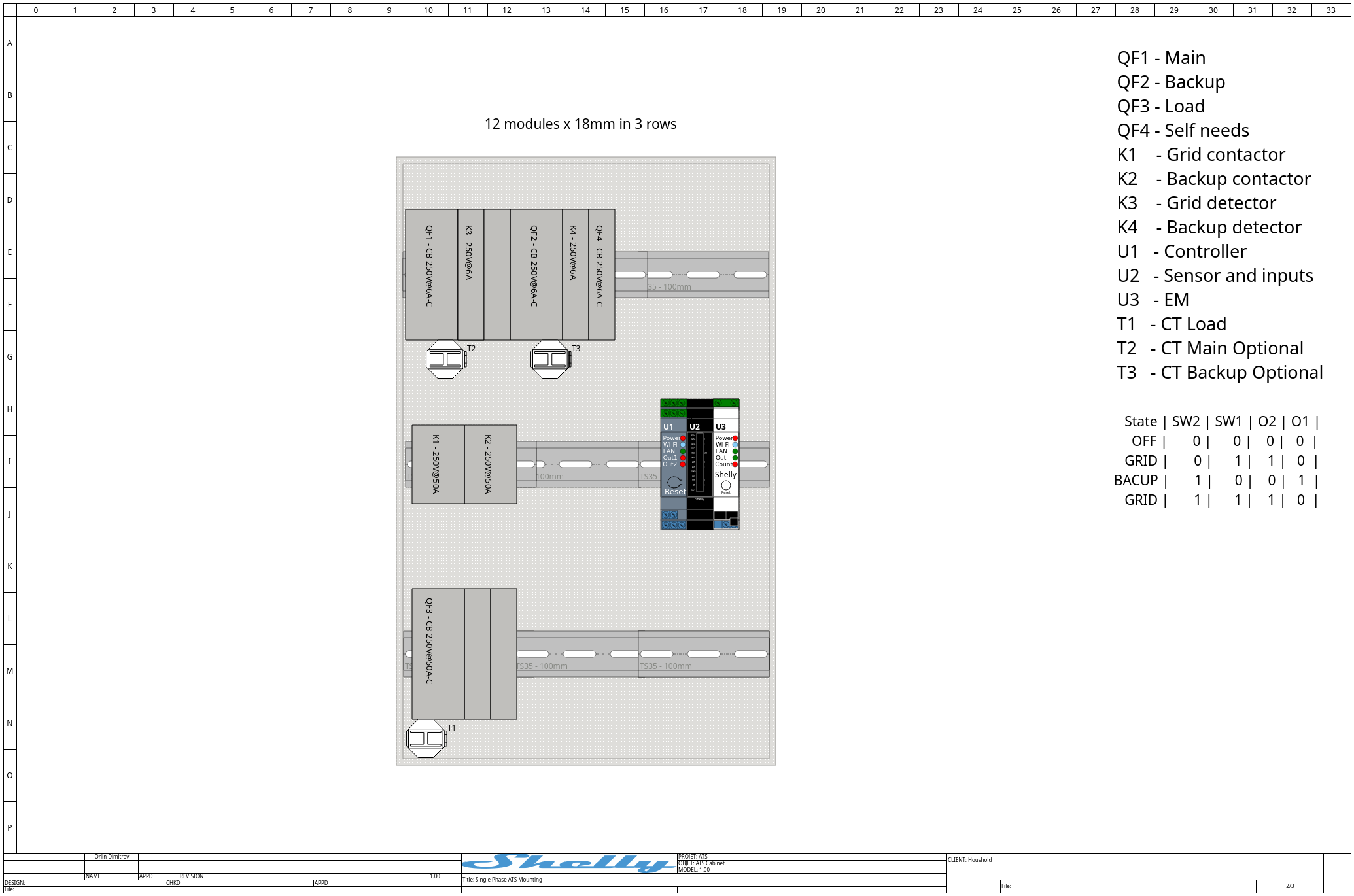
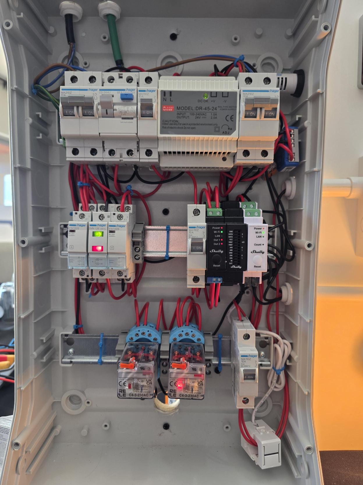
Disclaimer: The cabinet shown is a custom implementation with additional equipment. Its component arrangement differs from the proposed mounting diagram and should not be treated as the reference layout.
Three-Phase ATS
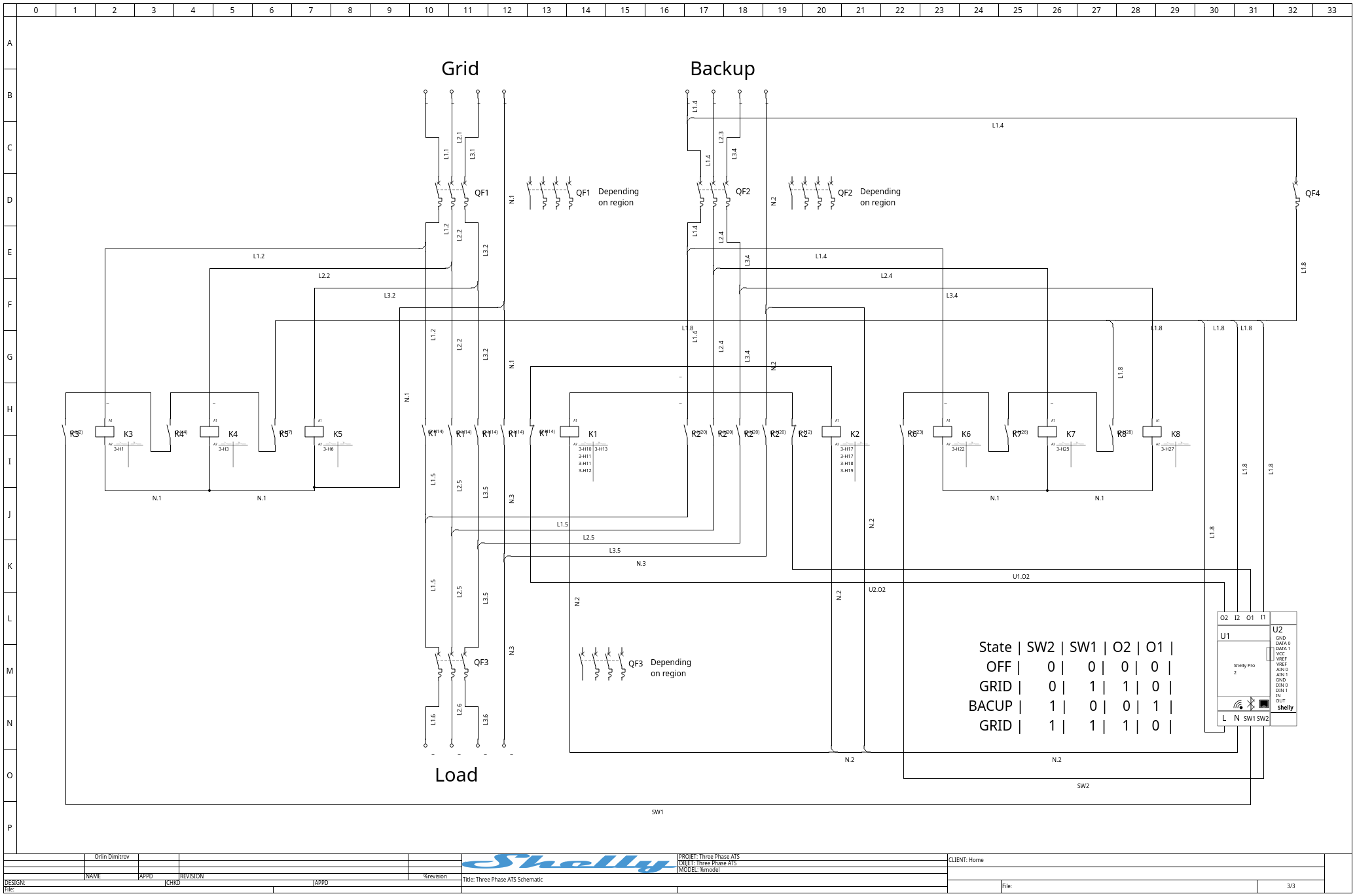
No universal mounting diagram is provided for the three-phase ATS. The physical layout is installer-defined because the dimensions, terminal positions, auxiliary contacts, heat dissipation, and spacing requirements of contactors K1 and K2 vary by manufacturer and model. The installer must prepare a cabinet layout that complies with the selected components, enclosure system, and applicable electrical regulations.
A finished three-phase cabinet photograph is not currently available. Its physical arrangement will depend on the installer-defined layout and the selected K1 and K2 contactors.
Core Materials
The use case is easier to understand when the materials are split into control, detection, transfer, metering, and cabinet construction.
Shelly Devices
|
Device |
What It Does In The Use Case |
|---|---|
|
Shelly Pro 2 ( |
Main controller. Reads source-availability inputs and drives the grid or backup contactor command. |
|
Shelly Pro Sensor Add-on ( |
Its inputs can provide auxiliary commands and states, including manual/automatic mode selection and grid/PV availability. Its outputs can activate alarms and status indicators. |
|
Shelly Pro 3EM 120A ( |
Measures energy/current values for visibility and demonstration. |
Cabinet And Demo Materials
|
Material |
Why It Helps People Understand The Use Case |
|---|---|
|
|
Connects the load to the grid source when grid is selected. |
|
|
Connects the load to the backup source when grid is unavailable and backup is present. |
|
|
Creates the grid-available signal used by the controller. |
|
|
Creates the backup-available signal used by the controller. |
|
|
Protects the cabinet's own supply/control branch. |
|
|
Protects the grid source branch. |
|
|
Protects the backup source branch. |
|
|
Protects the output/load branch. |
|
Current transformer |
Provides current measurement for the energy meter. |
|
DIN rail enclosure, terminal blocks, jumpers, wire, and ferrules |
Keeps source, control, and load wiring organized for demonstration and installation. |
|
Pilot lamps or panel indicators |
Shows grid available, backup available, selected source, and output state at a glance. |
Sales Angle
This is not only a backup-power accessory. It is a modular source-selection platform that makes the power path understandable, gives the preferred source priority, and provides a controlled fallback when that source is unavailable.
Sales Points
-
Expandable by design: Multiple cabinets can be cascaded to create a source-priority architecture for more complex sites without replacing the complete system with one custom transfer panel.
-
Works with the customer's energy ecosystem: ATS states, alarms, operating mode, and measurements can be integrated into Home Assistant, Homey, Node-RED, and other supervisory platforms.
-
Flexible second-source choice: The backup input can work with compatible battery, PV, hybrid-inverter, or other stable AC source systems instead of tying the customer to one vendor.
-
Local operation during network loss: Source selection remains inside the cabinet, so the core transfer logic does not depend on a cloud service or external automation server.
-
Clear for installers and service teams: Visible source detection, contactor states, metering, and modular stages simplify commissioning, fault finding, and future expansion.
-
Suitable for phased investment: A customer can begin with one grid/backup cabinet and add another transfer stage or information-system integration when the installation grows.
-
Safety remains hardware-backed: Software provides the decision logic, while correctly designed contactor interlocking, protection, and installer validation prevent unsafe source overlap.