
Overview
Shelly devices provide a local web interface that allows you to control and configure your devices through a standard web browser on either your computer or mobile device. With it, you can turn appliances connected to your device on or off, set schedules, and configure actions to execute when certain conditions are met.
Note that you do not need an internet connection or Shelly Cloud to use the local web interface - the only requirement is that your browser must be in the same Wi-Fi network as your Shelly device.
Accessing the web interface
To access the web interface:
-
Connect your device to a Wi-Fi network with a name (SSID) that follows this format: "DeviceName-XXXXXXXXXX", where ‘DeviceName’ is the name of the device you’d like to connect to, while 'XXXXXXXXXX' represents a unique combination of letters and numbers, constituting the device ID.
-
After establishing a connection to the device’s Access Point / AP (the Wi-Fi network mentioned in step 1), accessing the web interface is done by entering the universal IP address for all Shelly devices 192.168.33.1 in your browser.
You are now in the web interface of your device.
Connecting your device to a Wi-Fi network
Some of the settings you’ll see in the web interface are only available if the device is connected to the internet. To do that, follow these steps:
-
From the Web interface, navigate to Settings>Wi-Fi.
-
Either input or select your preferred Wi-Fi network and then enter its password. Alternatively, connecting to an open network is also an option, facilitated by selecting the checkbox for connecting to open Wi-Fi networks. Additionally, it is recommended to set a static IP address.
-
Allow your device a few seconds, so it can try to connect to the Wi-Fi network you provided. If the password you typed in is incorrect, or the Wi-Fi network lacks sufficient strength or stability, a message will be displayed in the web interface, notifying you that a connection couldn’t be established. Upon successful connection to the Wi-Fi, a link, containing the new IP address will appear as text above the Wi-Fi settings. Simply copy and paste this link into your browser.
You are now in the web interface of your internet-connected device. The next time you need to access the web UI, simply connect to the same Wi-Fi network as your device and type in the new IP address, obtained in step 3. Setting a static IP address is recommended because it guarantees consistent accessibility at that specific address.
Understanding the layout
The web interface can be divided into four main sections - the header, footer, main menu, and main content.
Header
The header consists of two components - the name of your device on the left and a few icons, which display your device’s main network and connectivity features on the right. These icons can encompass functionalities such as Wi-Fi, Bluetooth, MQTT, and more, as well as an icon that shows if there are any new firmware updates for your device. Hovering with your mouse on an icon will provide you with further information. You’ll find a legend with the meaning of each icon in the web interface guide of each device. Please note that the individual guides explain only the connectivity features available for that specific device.
Footer
At the bottom of the screen from left to right in order are the device model name, its ID, the version of the web interface, the firmware version of the device, and finally, the current time. If the time is not synced, you will receive a notification at the top of the screen, and some schedules and actions may not work as expected. Some previous versions of the web interface do not include all of these components.
Main menu
The main menu in the desktop version of the web interface is on the left, whereas on mobile, it looks like a hamburger menu with an icon of three horizontal lines, stacked on top of each other. The menu contains different items, depending on the device, but clicking an item from it takes you to a different page. You can also use it to get back to the Home page by clicking Home.
Main content
By clicking on an item from the main menu, you’ll be able to navigate through the web interface. Everything that you see on the screen, excluding the header, footer, and main menu is considered main content.
As the user interface might change over time, some screenshots might differ slightly from what you see in the web interface of the product.
Main menu
Below are explanations of each setting in the main menu, including what is visualized as main content upon clicking on the different settings.
In the web interface, you will see five icons in the header, including one for AP, Wi-Fi, Bluetooth, Cloud, and MQTT connection. Here is what the different status colors mean:

|
|

|
|

|
|

|
|

|
|

|
|
|
|
|

Home
In the Home page, you can view the live video streaming from your camera and adjust the streaming preview by using the following controls:
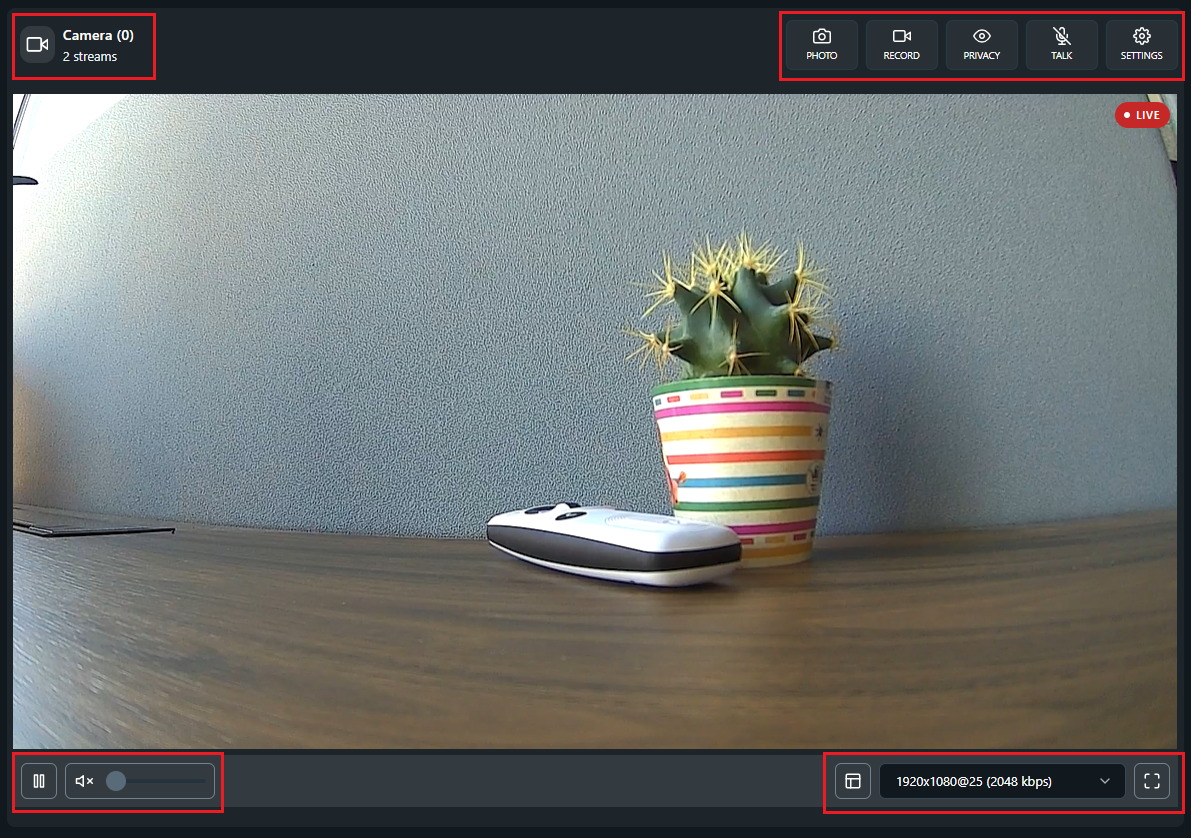
Live streaming controls:
-
Active stream viewers - shows the total number of video players currently open for this camera.
For example, if you open the video player on the Home page of the embedded web interface and, at the same time, in the Shelly Smart Control application, the count shows 2 stream viewing sessions. -
Photo - takes a snapshot from the live video stream. You can view all media files stored on your microSD card (if any microSD card is installed) in the Storage section.
-
Record - records a video clip from the live video stream. You can view all media files stored on your microSD card (if any microSD card is installed) in the Storage section.
-
Privacy - disables live streaming. While privacy mode is on, no live streaming or recording is available.
-
Talk - enables two-way audio communication through the camera.
To use this feature, configure the following camera settings:-
TLS configuration - uploads a valid certificate in the TLS configuration section so that the web interface can establish a secure connection required for two-way audio communication.
-
Speaker volume - adjusts the camera speaker volume to an audible level in the Settings menu.
-
-
Settings - opens the camera settings. For more information, see the How to configure your camera settings section in this document.
Video player controls:
-
Play/pause - starts or stops the video player
-
Volume control - adjusts the audio volume of the live streaming
-
Show zones - displays all configured motion and privacy zones
-
Select stream - selects whether to view Stream 0 or Stream 1. Each stream has different resolution configuration. For more information about how to configure the resolution of each stream, see the Video stream section in this document.
-
Full screen - expands the video player to full screen
How to configure your camera settings
The available camera settings enable you to configure your camera behavior based on your preferences.
To set up your camera, go to the Home page > Settings and use the different sections.
Name
Use this section to change the name of your camera. The camera component will be visible across the embedded web interface with the newly created name.
Image and video
Use this section to adjust the image and video quality settings to reflect the current environment.
Image settings
-
Adjust image appearance settings, including brightness, contrast, saturation, sharpness, tint, and color temperature.
-
Flip the image vertically or mirror the image horizontally.
-
Select the power line frequency rate, 50 Hz (Europe, Asia, Africa, Australia) or 60 Hz (North America, parts of South America), to match the local line frequency to avoid flickering under artificial lights.
Night vision
-
Switch between the following camera modes:
-
Auto - switch between day and night mode automatically based on the configured thresholds
-
Day - switch to day mode
-
Night - switch to night mode
-
-
Turn on infrared LEDs to illuminate the scene in complete darkness.
-
Set the light level at which the camera switches to Night mode. Higher values switch in brighter conditions.
-
Set how much the light level must change before the camera switches modes again. Lower sensitivity provides more stable switching and reduces repeated mode changes; higher sensitivity reacts to smaller changes.
Video streams
Your camera has 2 streams: Stream 0 and Stream 1. For example, you can use Stream 0 at high resolution when you need to retrieve high-quality video data, while simultaneously using Stream 1 at low resolution to monitor over a slow internet connection, where high image quality is not necessary.
For each stream, you can adjust the quality by configuring the following settings:
-
Resolution - select the stream resolution and frame rate, for example 1280x720@25, to fine-tune your video quality. Higher resolution and frame rate mean higher video quality, more details, and more storage space used.
-
Bitrate - select the stream bitrate in kbps (kilobits per second). Higher bitrate means better video quality and more storage space used.
Motion and recording
Use this section to configure your camera motion detection and recording settings.
Motion sensitivity
Configure how sensitive the camera is to detect motion: Very low, Low, Medium, High, or Very high.
Motion and privacy zones
Definitions list
-
Motion zone
The motion zone is a user-defined area within the camera's field of view; it is used for motion detection. -
Privacy zone
The privacy zone is a user-defined area within the camera's field of view; it is shown in black, blocks out that area in all video streams, and does not report motion.
The following actions are available per zone:
-
Add a new zone by clicking the Add zone button. When the zone appears on the screen, use the settings

-
Personalize the zone by setting up zone color and name.
-
Enable motion detection for this zone.
Record on motion
IMPORTANT: To record a video when motion is detected, make sure motion detection is enabled in the settings of the specific zone.
Enable the option if you want the camera to start recording automatically when a motion is detected.
Audio
Use this section to configure the audio settings of the camera.
Microphone
Enable audio input from the camera’s microphone by switching on the toggle.
Speaker
Adjust the volume level of the audio output. The default setting is 100%.
Camera sounds
Enable playing camera sounds when specific events occur, such as entering or exiting Privacy mode.
Device
Use this section to configure the following device operational settings.
RTSP streaming
Enable local access to the video streams of the camera over Real-Time Streaming Protocol (RTSP). Protect the access to your device by creating password in the Settings menu > Authentication tab.
LED indicator
Enable the status LED indicator on the camera.
Actions
Configure the actions for your device - create new actions, edit existing actions, or delete actions. When creating actions for your device you will need to specify the condition on which the action occurs. You can also set a duration for your actions, as well as a URL to be hit when the condition for the action is met.
Actions to execute
IMPORTANT: Make sure that you enabled motion detection for a specific zone in order to trigger an action within that zone.
The following actions can be executed when a trigger event happens:
-
Capture image - take a snapshot of the live video streaming when the set condition is met, for example, take a photo when motion is detected in the Main zone.
-
Start recording – record a video of the live video streaming when the set condition is met. Specify the duration of the recording between 1 and 3600 seconds.
-
Configure camera – configure the behavior of the camera when the set condition is met:
-
Motion detection property - select Armed or Disarmed. If the camera is Armed, you will receive a push notification when motion is detected.
-
Privacy mode property - select On if you want to disable the camera streaming when the set condition is met. You need to reactivate mode manually to enable streaming.
-
-
Play sound – select the type of sound property: Alarm, Ding Dong, or Notification. Make sure that the Camera sounds setting is enabled.
Schedules
This function requires a working connection to the Internet, so the device can synchronize the time. It allows you to create, view, edit, and delete schedules.
There are two types of schedules: Basic and Advanced.
To create a basic schedule:
-
Select the day(s) of the week.
-
Choose a time interval: time, sunrise, or sunset.
-
Set the time for the specified day(s):
-
Time: Click the up/down button, or type in a number, to set a time in hours and minutes.
-
Sunset/Sunrise: The Shelly device may turn on/off (or do specified action) automatically at sunrise/sunset, or at a specified time before or after sunrise/sunset. Click the up/down button, or type in a number, to set a time in hours and minutes.
-
To create an advanced schedule:
The advanced schedule function uses cron to execute jobs with a single schedule, instead of using a few basic schedules.
Creating an advanced schedule differs from creating a basic schedule, because of the When to execute menu.
It prompts you to select one or multiple values, a range of values, or a step between values (Choose one of the three by clicking on the Select, Range, or Step button for each value) for:
-
Seconds (0-59)
-
Minutes (0-59)
-
Hours (0-23)
-
Days (1-31)
-
Months (JAN-DEC)
-
Weekdays (SUN-SAT)
To create a schedule that happens every second/minute/hour/day/month/weekday, simply tick the box below the values in the desired section (seconds, minutes, hours, days, months, or weekdays). Additionally, you can use the sunrise/sunset offset by ticking the box next to this option. Doing so will bring up a new menu with hours and minutes. Leaving the hours and minutes and selecting either sunrise or sunset will make the schedule occur exactly at sunrise or sunset. Changing the hours and minutes values will create an offset, so entering negative values will make the schedule occur exactly [set hours and/or minutes] before sunrise/sunset while entering positive values will make the schedule occur [set hours and/or minutes] after sunrise/sunset. You cannot enter a positive value for one (hours/minutes) and a negative value for the other.
After that, simply specify the action you want your device to perform in the Actions section. Click Save once you’re done to save the new schedule.
In the Schedules menu, you can view all of your schedules. You can choose to view each one with basic or advanced time. Basic time shows the time and days that the schedule happens, while advanced time shows text in the Schedule card that tells you to click it for more information.
Both views display actions above. If there are more than three actions, they are displayed as +n where n is the remaining number of actions that is not displayed. To turn a schedule on/off, use the toggle button on the right.
Settings
Component settings
-
Camera - Edit the available camera settings. For more information, see the How to configure your camera settings section in this document.
-
Storage - Edit the following storage settings:
-
Name - Assign a user-defined name to the storage component.
-
Network storage - Configure storage to share files over the network using the NFS protocol.
-
Format storage - Erase all data on the inserted microSD card and prepare it with a new file system.
-
Eject storage - Safely unmount the inserted microSD card before physical removal to prevent data corruption or loss.
-
Network settings
-
Access point - Configure the device's access point (AP) by selecting the Enable access point checkbox and setting a password to secure your network from unauthorized access. The access point of the device is an open network by default. The SSID is unique and cannot be changed.
-
Wi-Fi - Register the Shelly device to connect to up to 2 different Wi-Fi networks.
Either input (through writing in the text field) or select the Wi-Fi network by clicking on the chevron (arrow) icon to browse through all available networks. You can also select an open network, and also set a static IP address.
Enable Wi-Fi 1, or Wi-Fi 2, or both at the same time (by using the toggle next to each one). If both Wi-Fi 1 and Wi-Fi 2 are enabled, and the Shelly device disconnects from one of the networks, it will connect to the other. It is possible to enable Wi-Fi only once the network name (SSID) is set. If the device has no other connections available (AP, Bluetooth, Ethernet (if it applies), or a second Wi-Fi network), trying to disable the Wi-Fi will cause a pop-up asking you if you wish to continue. -
Bluetooth - Bluetooth activates automatically when your device needs it and turns off when not in use to save power. You can use the tab to perform the following actions:
-
View the MAC address and Bluetooth status: Active or Inactive
-
Select the Bluetooth device control checkbox to allow other devices to control your Shelly device via RPC over Bluetooth. Only the devices that you paired can connect.
-
Click the Pair new device button to pair another device to your Shelly device.
-
Connectivity settings
Note: When an RPC call fails to be executed, a banner message appears - it notifies you that the device is not responding in time, and has lost connection. When the connection is restored, the request will be sent again.
-
Cloud - Connecting your Shelly to its cloud allows you to control it remotely and receive notifications and updates about your devices. The setting is enabled by default.
IMPORTANT: If you disable the device cloud support, you will lose connection to your device from outside its local network.
-
MQTT - Configure the Shelly device to execute actions via MQTT. By default, MQTT is disabled, but you can enable it by selecting the empty checkbox. Changing these settings will cause the device to reboot.
There are some other settings, such as RPC status notifications over MQTT (which enables you to communicate with your device through RPC notifications) and Generic status update over MQTT (to get an overall status update), which you can enable or disable. You can also enable SSL and type in your server, username, and password, but be aware that enabling SSL will hurt the battery life and most likely shorten it by half. -
RPC over UDP - Communicate with your device and send requests through a Remote Procedure Call (RPC) over a User Datagram Protocol (UDP) server. This can be useful in controlling and monitoring your device remotely, without the need for a dedicated server or connection.
To use this setting, you'll need to enter the listen port and destination address for the UDP server. The listen port is the port number that the device will listen on for incoming requests, while the destination address is the IP address of the server to which the requests will be sent.
Once you've entered the required information, you can use the RPC over UDP protocol to send requests to your device and receive responses.
-
Outbound WebSocket - Enable the device to connect to the configured WebSocket server and start transmitting events. To configure the WebSocket server, select a connection type from the dropdown menu and then enter the server address.
Device settings
-
Device name (info) - See your device’s ID, the Wi-Fi it’s connected to, and the Wi-Fi RSSI.
-
Reboot device - After clicking on the Reboot button, you will be asked if you’re sure you want to reboot your device. Click OK for device reboot and Cancel if you don’t want the device to reboot.
-
Factory reset - By clicking on the Reset button, your device’s settings will all be reset to the default. Any changes you’ve made will be reverted. You can confirm that you want the device to factory reset by clicking OK on the pop-up, or Cancel to cancel the factory reset.
-
Location and timezone - Your timezone and location will be autodetected, but you can manually change them from this setting by choosing a timezone from the drop-down menu and typing in your latitude and longitude. There is also a button Auto detect location, which will make the device automatically detect the location once again if it failed the previous time.
Note: If the device’s time is not synced with the current time, schedules and actions may not work as expected. A message will appear to let you know if the time is not synced.
-
Authentication - If you enable authentication, you will be asked to type in a password, which you will then use to access the Web UI of the device. Once enabled, to disable it, click the toggle and enter your authentication pass once prompted.
-
Firmware - In this setting, you can see your device's ID, firmware version, build ID, and web build ID. Use the Copy button above the firmware ID or the web build ID to copy the contents to your clipboard. You can also see the available new versions, check for updates and easily update your device. There is also an option to upload your own firmware, however flashing devices with custom firmware irreversibly voids the device warranty.
-
Debug - This setting includes Mqtt, Websocket, and Udp debug. To enable any of these, click the toggle switch next to the specific setting. For Udp debug you will also be asked to type in a Udp address.
-
TLS configuration - In this section, enhance communication security by uploading a TLS server certificate, a custom client certificate, or an HTTPS certificate to enable certificate-based authentication. For more information about how to obtain a certificate, go to https://shelly-api-docs.shelly.cloud/gen2/General/CustomHTTPSCertificates/.
-
Appearance - In this section, you can switch the web interface to a darker colour theme for more comfortable viewing in low-light environments.
Scripts
This device features scripting capabilities. You can use them to customize and enhance device functionality based on a user’s specific needs. These scripts can take into consideration device state, communicate with other devices, or pull data from external services like weather forecasts. A script is a program, written in a subset of JavaScript.
In the web UI, when you go to the Scripts menu, you will see the existing scripts, or if you don’t have any, you can create one, or open the library to explore what is already available. Next to each script you have, you will be able to see its status (whether it’s running or stopped), and a toggle allowing you to run the script on startup. If your script has any errors, the last saved error will be shown under the script’s name.
When you are in the editing view of the script, you will see the console underneath, as well as any errors that pop up. Above the code field are options to Save, Start/Stop, or Delete your script. You can also access Snippets and Docs by clicking on the corresponding labels.
Components
Creating a component
The Components setting allows the user to create Dynamic Components, which don’t initially exist in the device. Virtual components, a type of dynamic component, are used to store or transfer data between scripts or runs and display the script’s functionality on the home page. Components can be grouped together; only the groups and the components inside of them will be displayed on the home page. Components that don’t belong to a group will not be visualized there. The number of components and groups of components per device is limited.
To create a component:
-
Click the Create new button next to User-defined components.
-
Select the type of component you’d like to create - Boolean, Number, Text, Enum, or Button. When created, each component type has Name, View, and Custom Icon URL fields, which you have to fill in. The Custom Icon URL field isn’t required, but it can be used to customise how your components look in the home page. You can rename or delete a component, as well as create actions for it, using the buttons located next to each component.
The different component types may have additional fields, specific to that type. They are explained below
The Boolean component type stores a true/false value and has two different titles that the user can enter depending on if its value is true or false, as well as two separate icons. The drop-down menu for the default value will include the different states of your device. The view options are Hidden, Toggle, and Label. The Toggle view displays a toggle button, so the component’s value changes on each hit. The Label view shows the title for the component’s value.
The Number component type stores values between -999999999999999 and 999999999999999. The default value should be a number in this range. You can also change the unit and step. The view options are Hidden, Field, Slider, Progress bar, and Label. The Field view shows an input field, the Label view displays the value, the Progress bar view visually represents progress, and the Slider view displays a slider interface for interaction.
The Text component type stores a string with up to 255 characters. The view options are Hidden, Field, Label, and Image. The Field view shows an input field, the Label view displays the title, and the Image view requires a URL value, which it uses to display an image.
The Enum component type stores a group of named constants. The view options are Hidden, Dropdown, and Label. If you select Label view, the component will display the title by default, but if an image is specified, it will take precedence and be shown instead.
The Button component type provides a simulated virtual input that allows users to interact with the user interface by registering and reporting clicks. It then sends notifications through connected channels and can be used to trigger automations, and activate webhooks. It features two view options - Button, which displays the button component in your home page, and Hidden.
If a component is set to Hidden, it won’t be displayed in the home page. Otherwise, your component groups will appear below your device’s input(s) and/or output(s) and will display the components, which are part of those groups.
Creating a group of components
To create a group:
-
Click on the + next to User-defined groups, and you’ll be taken to the group creation menu.
-
Enter the name of the group.
-
Select the desired components that you’d like to have in that group.
Editing your groups menu is done through the pencil icon next to the + and it allows you to change the order of your groups by clicking on the up and down arrows to move a group up or down.
Component actions
The Actions menu is now structured based on component type. So, you can create actions for your components and they’ll be separated into the aforementioned five categories.
Scripting
Components can be included in scripts and programmed to change values depending on a condition. To specify a component in a script, you’ll need to use its ID. Component IDs start from 200 and are limited to 299. You’ll be able to see your component’s ID in the Components menu.
Storage
In the Storage section, you can view all media files stored on your microSD card (if any). You can view, download, or delete a specific file.
For more information about how to configure your storage settings, go to the Component section > Storage section in this document.
Advanced Settings
Upon clicking on the arrow next to this setting, you will reveal the advanced settings. They are explained below.
KVS
KVS stands for Key-Value Storage and is a type of non-relational database, which works by using a simple key-value method to store data. In one device, you can store up to 50 key-value pairs. Upon clicking on the Add value button, you will be taken to the value creation screen, which prompts you to enter a key (up to 42 characters), and value (up to 253 characters). You’ll notice under the text box for the value is the current value type. By default, the value type is Number, but by entering text, the type will change to String. To save the key, simply click the Save button. To edit an existing value, simply click on it. To delete a key-value pair, click the Delete button that appears below it when you go to edit the key. Clicking on the question mark next to the setting name will take you to the API documentation, which will provide you with further information on how the KVS works for Shelly devices.
Diagnostics
From this setting, you can download the debug logs. Enabling the debug log without a reason isn’t recommended, since your device will be slowed down and this setting will cause aging of the flash memory. If you do decide to enable it, you can also download the previous and current logs. Be aware that leaving this page will reset the logger and log data.
HTTP ping
Enter a URL in the designated text field to send an HTTP request to it from your device. The web interface will then let you know if the request was successful or failed.
Device clients
View the devices connected to your device, and sorted in the proper category. There are two options for most devices:
-
Bluetooth clients - devices connected to your device through Bluetooth.
-
AP clients - devices connected to your device’s Access Point.
In this menu, you’ll be able to see information about the clients.