Integration of Shelly & Shelly PRO devices within existing KNX infrastructure
Introduction
In the following example we are going to describe the ease of use and the benefits of using Shelly and Shelly PRO series when we need to replace one or more faulty KNX devices.
Most of the KNX users are familiar with the unpleasant situation when for any reason (e.g. lighting strike, short circuit, overload and etc.) one or more channels of a switching actuator become out of order. Usually, in such cases, there are two possible solutions:
To replace the faulty actuator with a new one simply because there are no spare channels available and no combinations of controlled circuits are possible. This scenario becomes an expensive one especially if it concerns replacing a unit consisting of eight or more channels in it.
Second option is simply to reorganize and combine the existing circuits in such a way to keep all of them automated for no additional cost. Probably most of you have already guessed, but it’s worth mentioning that a solution like this limits the ability of separate circuit control and causes comfort suffering in the end.
Like we stated in the beginning, out aim with this example is to give you not only another solution, but to keep it simple too.
Prerequisites
Shelly devices are able to communicate with other KNX devices using KNXnet/IP communication. Assuring the necessary equipment is a must in order to use our devices. For more detailed information on using Shelly devices with KNX read the documentation provided.
Get to know the Shelly PRO series and there specifications by reading and understanding the User manual provided with the devices of your choice.
General description
Here we are going to review not a single case and a single device, but several cases and devices of Shelly’s PRO range, which consist of DIN rail mountable devices. As such devices they are meant to be used inside electrical distribution boards designed for home/office and/or industrial automation solutions.
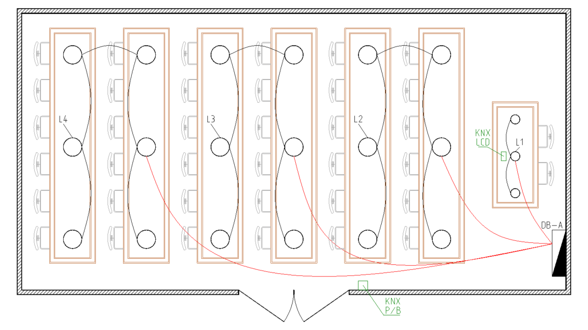
For this purpose we are using a sample conference room shown on Fig. 1.

Initially the Conference room was accomplished using only KNX equipment, which is part of the automation system of the whole building. The rest of the system is not of our concern for this case and its sub-cases presented here. What is important to us is that the electrical installation of the building is designed according to the requirements of the KNX automation system and centralized control of the building is provided, i.e. a KNX server is present.
Detailed information about used KNX equipment for control is described in Table 1.
Table 1 - KNX equipment | ||
|---|---|---|
Device | Location | Description |
4 channel switch actuator | DB-A | Controls all lighting circuits (L1 - L4) |
4 fold push button | Conference door | Recalls room scenarios |
KNX control display | Presenter desk | Individual control; Recalls & Saves scenarios |
Further details about each lighting circuit in this room and also the used KNX Group addresses for control and monitoring (feedback) are provided in Table 2.
Table 2 - Lighting circuits description and KNX Group addresses used | |||||
|---|---|---|---|---|---|
Name | Description | Control type | Control channel | Command GA | Feedback GA |
L1 | Presenter spots | ON / OFF | Sw. actuator, channel 1 | 1/1/1 | 1/2/1 |
L2 | Seats front lights | ON / OFF | Sw. actuator, channel 2 | 1/1/2 | 1/2/2 |
L3 | Seats center lights | ON / OFF | Sw. actuator, channel 3 | 1/1/3 | 1/2/3 |
L4 | Seats back lights | ON / OFF | Sw. actuator, channel 4 | 1/1/4 | 1/2/4 |
Now let’s have a look to the drawing in Fig.1 and make it a bit more clear. The red lines in the drawing shows that the wires of every lighting circuit in the room is feed from the distribution board (DB-A). This means that the supplying wires are not interrupted by any wall switches. With green color are shown the KNX control points, which also end in the panel (not shown).
Using the described setup, let’s dive into the deep and review the following sub cases:
