Outputs
Shelly devices containing an output switch or light component have built in associated input for user input for control. When using device outputs for integration into a KNX system the recommendation is to de-associate the input from the output and continue with the described configuration method below.
In case the pair of input and output can not be de-associated keep in mind that the internal to the Shelly device logic and the logic implemented in the KNX system will execute in parallel.
Regardless of the configuration of the Input/Output settings, every output represented into KNX as Switch object always have the following KNX access flags:
-
write - other KNX devices may write to this object
-
transmit - object transmits state upon every status change to the KNX network
In the right side of every Group address field two buttons are available - Save and Delete, giving you the option either to save or delete the entered configuration.
Keep in mind that entered Group addresses must share the same DPT type. Shelly embedded web interface can not check that!
Up to three Group addresses may be added for every command object, which represents an output. These command objects inherit the access flags mentioned above.
Each Group address assigned represents separate command object, meaning that it has its Sending attribute always Enabled, a.k.a. Sending Group Address!
The Group address assigned to Feedback object is used to “write” the current state of Shelly Output, i.e. ON or OFF.
Only one Group address may be assigned to Feedback object.
How to configure an Input to be detached from an Output
To limit side effect of internal to the Shelly device logic conflicting with the KNX programmed logic this is the recommended mode of operation.
Navigate to the Output configuration, Input/Output settings and select the Detached option
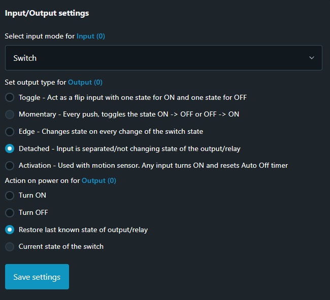
NOTE: In case device inputs are not used disregard this step.
Configuring Output Component for KNX Communication
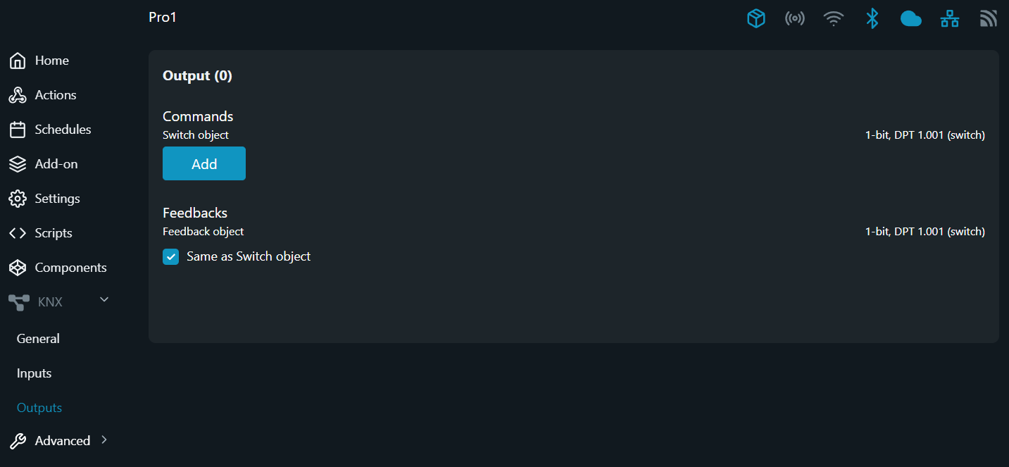
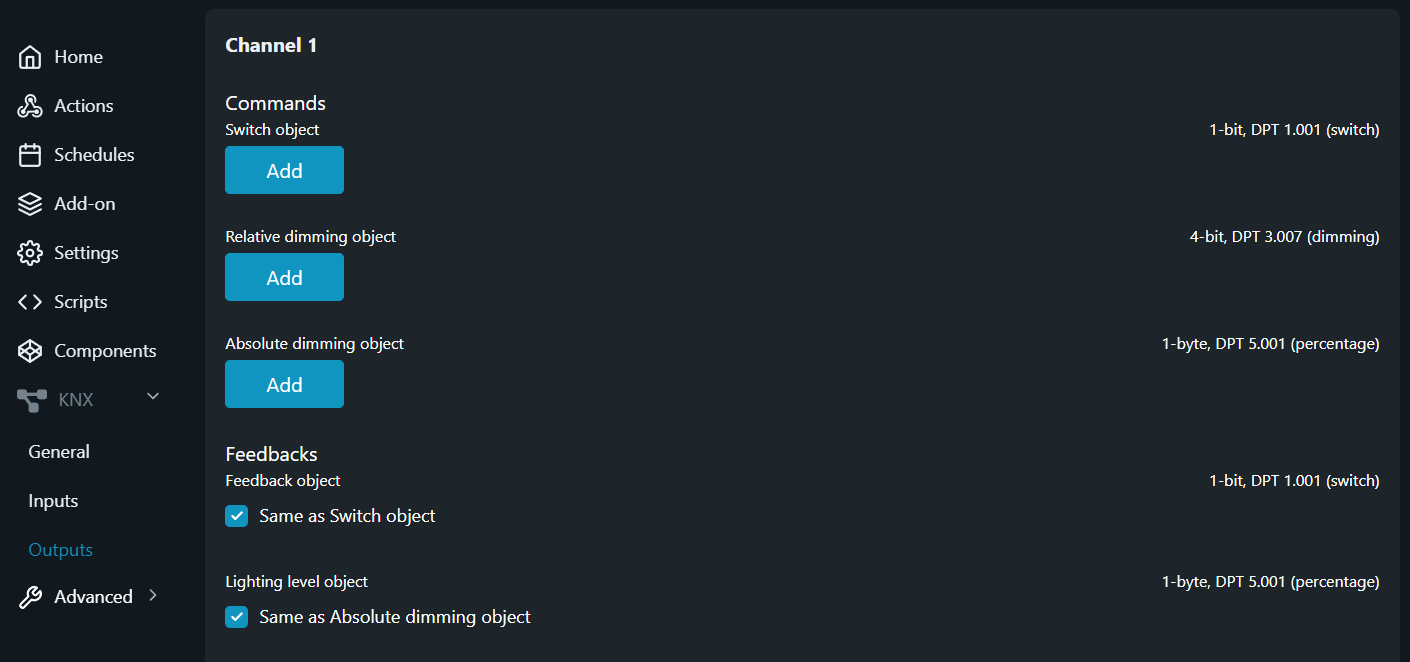
Navigate to the KNX configuration section and select Outputs from the menu.
Configure the switching actuator
Step 1 - Switch object
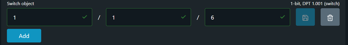
The Switch object is used to command the state of the output relay. The relay is energized by receiving logical “1” and de-energized respectively with logical “0”.
Encoding: 1-bit; DPT 1.001 (switch)
To add aGroup address to the Switch object press the Add button. Provide the desired Group address in the newly appeared field and then click on Save button.
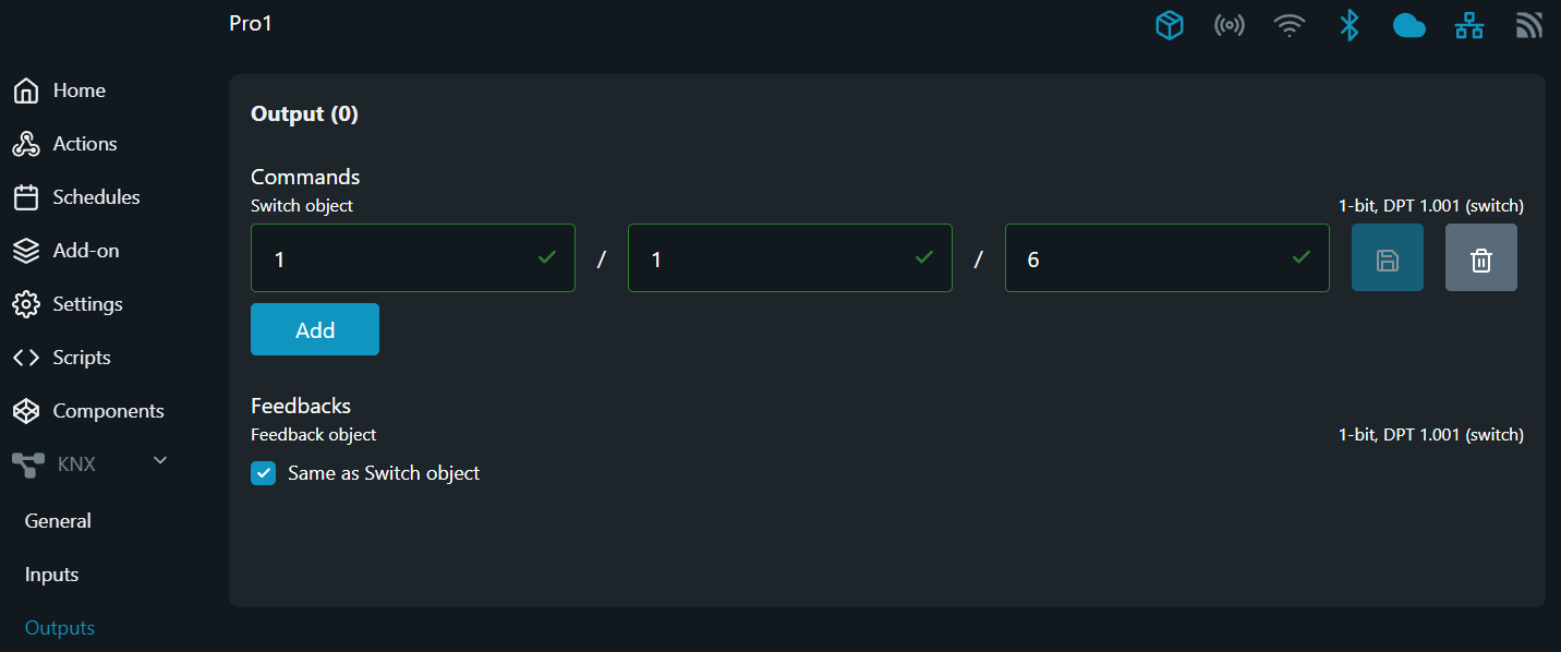
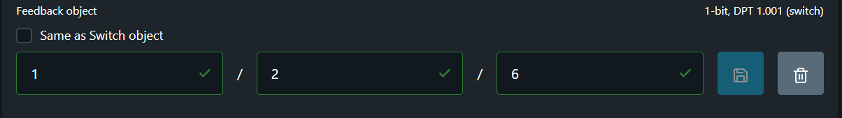
Step 2 - Feedback object
The Feedback object serves to provide the state of the output relay (energized/de-energized) to other KNX devices present in the given Group address. By default the check-box for Same as ... object is active, meaning that the device is going to "write" its own state upon every change at the Group Address provided in the Switch object field.
If you wish to add separate Group Address to the Feedback object you should uncheck the check-box Same as ... object and add the desired address in the fields provided below it. To save the new added configuration click on Save button.
Encoding: 1-bit; DPT 1.001 (switch)
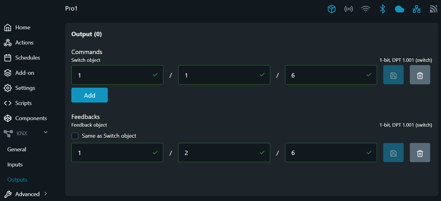
NOTE: In case more than one Group address is provided for Switch object command and the check-box for Same as ... object is active, the the status of the output channel is provided to the first Group address field only!
Configure the dimming actuator
Step 1 - Switch object
Shelly dimming output uses the Switch object simply to command the state of the output - ON or OFF. The output is energized by receiving logical “1” and de-energized respectively when a logical “0” is received.
Encoding: 1-bit; DPT 1.001 (switch)
To add aGroup address to the Switch object press the Add button. Provide the desired Group address in the newly appeared field and then click on Save button.
Step 2 - Relative dimming object
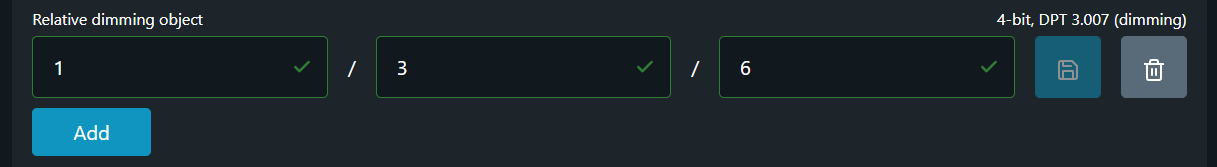
A Relative dimming object allows for adjusting the brightness level of dimmable lights relative to their current state, enabling incremental/decremental adjustments for lighting control. The step value (currently set to full always, see note below) of the brightness change and the dimming direction are defined by the telegram value.
The output channel can only be switched on by relative dimming telegrams. If it is switched on and the setpoint falls below the value set in Minimum brightness on toggle in % using relative dimming telegrams, the output remains switched on at the given dimming value. When the channel is switched off and on again it starts with the preset value in Minimum brightness on toggle.
After a relative dimming telegram has been received, a new nominal value is calculated using the current value, the received dimming direction and the received step value.
Encoding: 4-bit; DPT 3.007 (dimming)
To add aGroup address to the Relative dimming object press the Add button. Provide the desired Group address in the newly appeared field and then click on Save button.
NOTE: Shelly dimmer actuators controlled via Relative dimming object currently support full dimming step only!
When a telegram containing Relative dimming object with encoded dimming step other than full is received, the step information is disregarded and the dimming output is always in full range.
Step 3 - Absolute dimming object
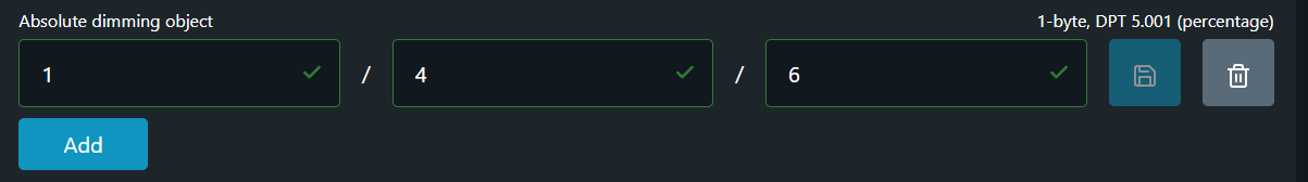
The absolute dimming function is used to set the required brightness directly. To do this, the Absolute dimming object of the command channel sends the desired brightness value as a percentage between 0% and 100%. The value range is divided up into 255 brightness levels. A level has a step value of approximately 0.4%. The telegrams for dimming with absolute values have a 1-byte data format (0 to 255).
The desired brightness values may fall below the limit which is defined by the Minimum brightness on toggle only if the channel is switched on. When the channel is switched off and on again it starts with the preset value in Minimum brightness on toggle.
This parameter setting prevents switching, i.e. the channel remains at the current value.
Encoding: 1-byte; DPT 5.001 (percentage)
To add aGroup address to the Absolute dimming object press the Add button. Provide the desired Group address in the newly appeared field and then click on Save button.
NOTE: Some visualization distributions (KNX servers) expect standard behavior related to this object, i.e. any manipulation of Absolute dimming object should turn ON the controlled channel to the given value, which is not the case with Shelly dimmers. Such manipulation may lead to desynchronization between the controlled channel and the visualization software used.
Step 4 - Feedback object
The Feedback object always corresponds to the current output state (ON or OFF). Dimmed corresponds to the ON setting. Every time the state changes from OFF to ON or vice versa, the current object value is sent to other KNX devices present in the given Group address. By default the check-box for Same as ... object is active, meaning that the device is going to "write" its own state upon every change at the Group Address provided in the Switch object field.
Encoding: 1-bit; DPT 1.001 (switch)
If you wish to add separate Group Address to the Feedback object you should uncheck the check-box Same as ... object and add the desired address in the fields provided below it. To save the new added configuration click on Save button.
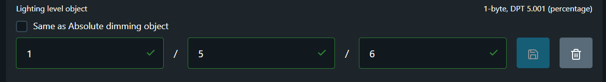
Step 5 - Lighting level
A Lighting Level object provides real-time feedback on the current brightness level in percentage of the dimmer output, allowing users to monitor lighting levels accurately. By default the check-box for Same as ... object is active, meaning that the device is going to "write" its own state upon every change at the Group Address provided in the Absolute dimming object field.
Encoding: 1-byte; DPT 5.001 (percentage)
If you wish to add separate Group Address to the Lighting Level object you should uncheck the check-box Same as ... object and add the desired address in the fields provided below it. To save the new added configuration click on Save button.
Configure the Blind or Roller shutter actuator
Supported Devices
Cover control mode (blind or roller shutter actuator) is available for the following Shelly devices:
-
Shelly 2PM (Gen 3 and later)
-
Shelly PRO 2PM
-
Shelly PRO Dual Cover
For supported devices, open a web browser and go to the embedded web interface at http://192.168.33.1, or refer to the detailed instructions here.
Then, navigate to Settings → Device Profile, enable Cover Mode, and click Save (see Figure 1 below).
After the device automatically reboots, it will operate in cover control mode.
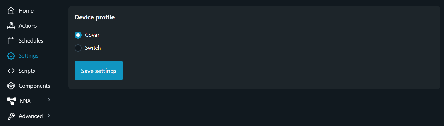
Once Cover Mode is enabled, go to Settings → KNX → Outputs to configure the KNX settings for the device.
Note: The KNX feature must be enabled, and the related General Settings should be preset beforehand.
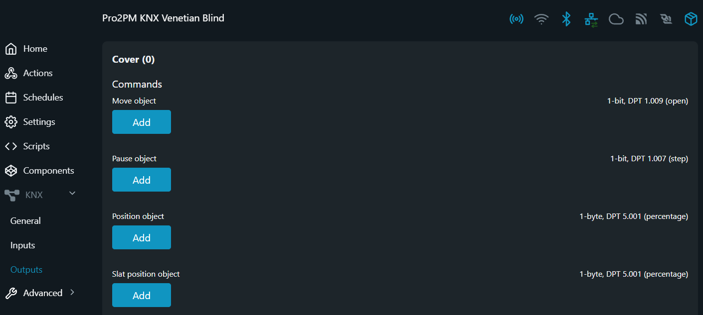
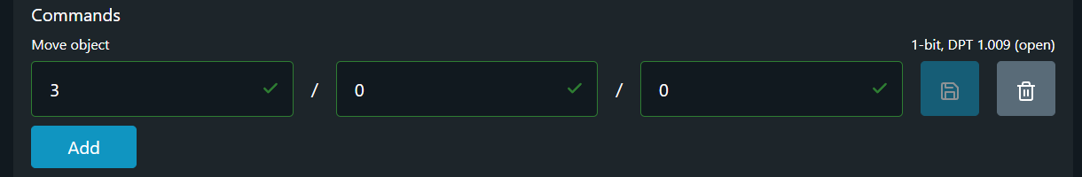
Step 1 - Move object
The Move object is responsible for opening and closing the cover (blind or roller shutter up and down respectively). The drive closes the cover if the value “1” (blind or roller shutter down) is received and opens (blind or roller shutter up) it when the value is “0”. If a control command in the opposite direction of motion is received while the drive is moving, then the drive stops and waits for the defined idle time (see Idle settings here) before starting to move in the new direction of motion.
The output responsible for the direction of movement stays active until one of the following occurs:
-
the cover reaches its end position, or
-
a control command for changing the direction of motion is received while the drive is moving, or
-
a telegram is received on
Pause object, or -
an obstacle is detected (see Obstacle detection here)
The output operation time is automatically defined once the cover is calibrated.
NOTE: The cover calibration is possible for motors that report power metering only!
When motors that don't report power metering are used (e.g. DC motors), Movement time limits apply. See details here.
Encoding: 1-bit; DPT 1.009 (open)
To add aGroup address to the Move object press the Add button. Provide the desired Group address in the newly appeared field and then click on Save button.
You can assign up to three (3) Group Addresses to the Move object.
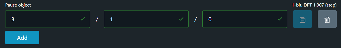
Step 2 - Pause object
A drive that is in motion is stopped on receiving a bus telegram at Pause object. The value received for this object is irrelevant here.
NOTE: If a control command in the opposite direction of motion is received while the drive is moving, the drive stops and waits for the defined time delay when changing directions. See Idle settings here.
Slat Control (Venetian Blinds):
When Slat Control is Enabled, the slat angle can be incrementally adjusted via the Pause object. With every received telegram on the Pause object ("0" or "1"), the slats are driven by a step value defined under Cover settings → Slat control → Step.
A “0” value received drives the slats toward the open position, while value of “1” drives them toward closed position.
If a step command is received while the slats are already at one of their movement limits, the drive will not react to the received command.
NOTE: Slat angle adjustment is only possible when the motor is not running.
Encoding: 1-bit; DPT 1.007 (step)
To add aGroup address to the Pause object press the Add button. Provide the desired Group address in the newly appeared field and then click on Save button.
You can assign up to three (3) Group Addresses to the Pause object.
Step 3 - Position object
The Position object is responsible for the position of the cover (blind or roller shutter). Limit position 0% means that the cover is fully open (blind / roller shutter is at the top). Limit position 100% means that the cover is fully closed (blind / roller shutter is at the bottom).
Upon receiving new positional value at the Position object, the cover determines which output is to be activated and calculates a running time needed to reach the new position from the current position. The drive is then moved to the new position for the calculated duration. If the device receives a new positional value during a positioning movement and the calculation results in the same direction of motion, the drive continues moving to the new command position. If a new positioning command is received during a drive motion and the calculation results in the opposite direction of motion, the drive stops and waits for the defined in Idle settings time (see details here) before starting the new positioning movement.
Encoding: 1-byte; DPT 5.001 (percentage)
To add aGroup address to the Position object press the Add button. Provide the desired Group address in the newly appeared field and then click on Save button.
You can assign up to three (3) Group Addresses to the Position object.
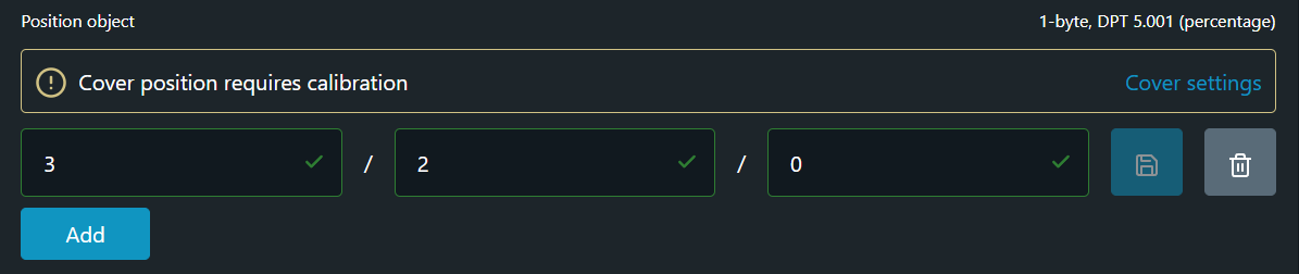
NOTE: The cover needs calibration to determine its position accurately. If the cover needs calibration an information panel is displayed above the Group address field.
Until calibrated, positioning commands received at the Position object will be ignored.
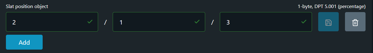
Step 4 - Slat position object
NOTE: The Slat position object becomes visible only if Slat control (Venetian Blinds) is Enabled.
To enable Slat Control, go to the device settings through the embedded web UI. Then navigate to Cover Settings → Slat Control, set it to Enable, and press Save Settings.
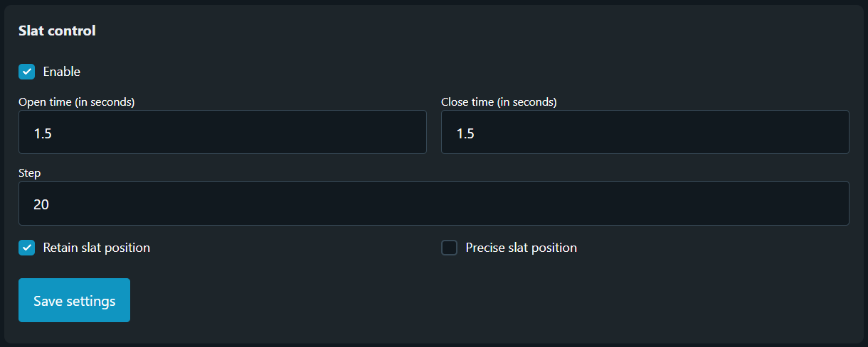
-
Open Time
Time it takes for slats to move from fully closed (0%) to fully open (100%) position, in seconds.
Must be manually configured by the user.
Accepted range: [0.5 … 30] s — Default: 1.5 s -
Close Time
Time it takes for slats to move from fully open (100%) to fully closed (0%) position, in seconds.
Must be manually configured by the user.
Accepted range: [0.5 … 30] s — Default: 1.5 s -
Step (%)
Defines the tilt adjustment step size as a percentage of the full slat range.
Each command changes the slat position by this percentage.
This value also determines the amount by which the slats move each time a command is received via the KNX Pause object.
Must be manually configured by the user.
Accepted range: [1 … 100]% — Default: 20%
NOTE: The percentage definitions used by Shelly are the exact opposite of those used in KNX objects.
For example, a 0% slat position in Shelly corresponds to 100% in KNX, and vice versa. Make sure to account for this when integrating between systems.
-
Retain Slat Position
Determines whether the slat position is restored after a change in the cover (vertical) position.
When enabled, the slats will temporarily move to a neutral tilt angle that allows vertical motion. Once the vertical movement completes, the drive will execute an additional movement to return the slats to their previous tilt position.
Options: Enabled / Disabled -
Precise Slat Position
Improves slat positioning accuracy when the cover is close to the fully closed position.
This setting only takes effect if the current cover (vertical) position is less than one full slat rotation away from fully closed.
In this case, any slat movement will first move the cover to the fully closed position before applying the slat tilt change.
This results in more accurate slat alignment but increases operation time.
Options: Enabled / Disabled
TheSlat position object can be used to set the slat opening angle directly.
Please note that the actual slat position varies depending on the type of Venetian blinds used. There are four supported blind types, classified by their slat movement behavior:
-
Downwards closed / Upwards horizontal
-
Downwards tilted / Upwards horizontal
-
Downwards closed / Upwards closed
-
Downwards tilted / Upwards closed
The table below shows how the percentage values (0–100%) of the Slat Position object correspond to actual slat angles for each blind type.
Each type is explained in detail in the sections that follow, including diagrams for better understanding.
|
|
Blind type: Downwards closed /
|
Blind type: Downwards tilted /
|
Blind type: Downwards closed /
|
Blind type: Downwards tilted /
|
|---|---|---|---|---|
|
Slat position
|
Horizontal
|
Horizontal
|
Top
|
Top
|
|
Slat position
|
Bottom
|
Bottom
|
Bottom
|
Bottom
|
-
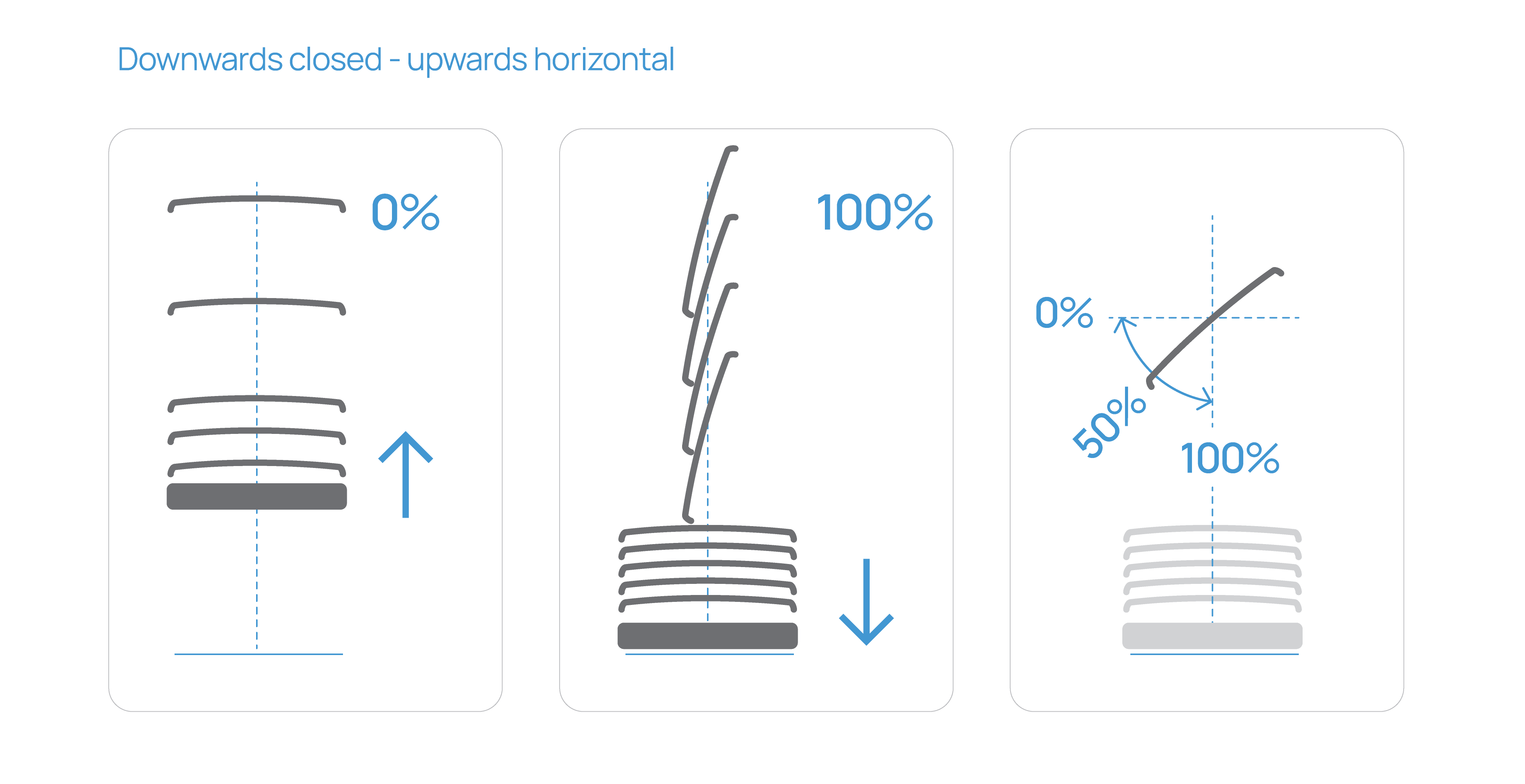
Downwards closed / Upwards horizontal
In this configuration, “Downwards Closed” means that when the blind is moving downward, the slats are tilted shut, blocking light completely.
“Upwards Horizontal” indicates that before the blind begins moving upward, the slats first rotate to a flat, horizontal position—this is the maximum slat opening, allowing full light entry. Only after reaching this position does the blind begin its upward movement. The slats do not rotate beyond horizontal; there is no upward tilt past this point.
See Figure 8 for visual representation, illustrating how the 0–100% Slat Position values map to actual slat angles for this type.
-
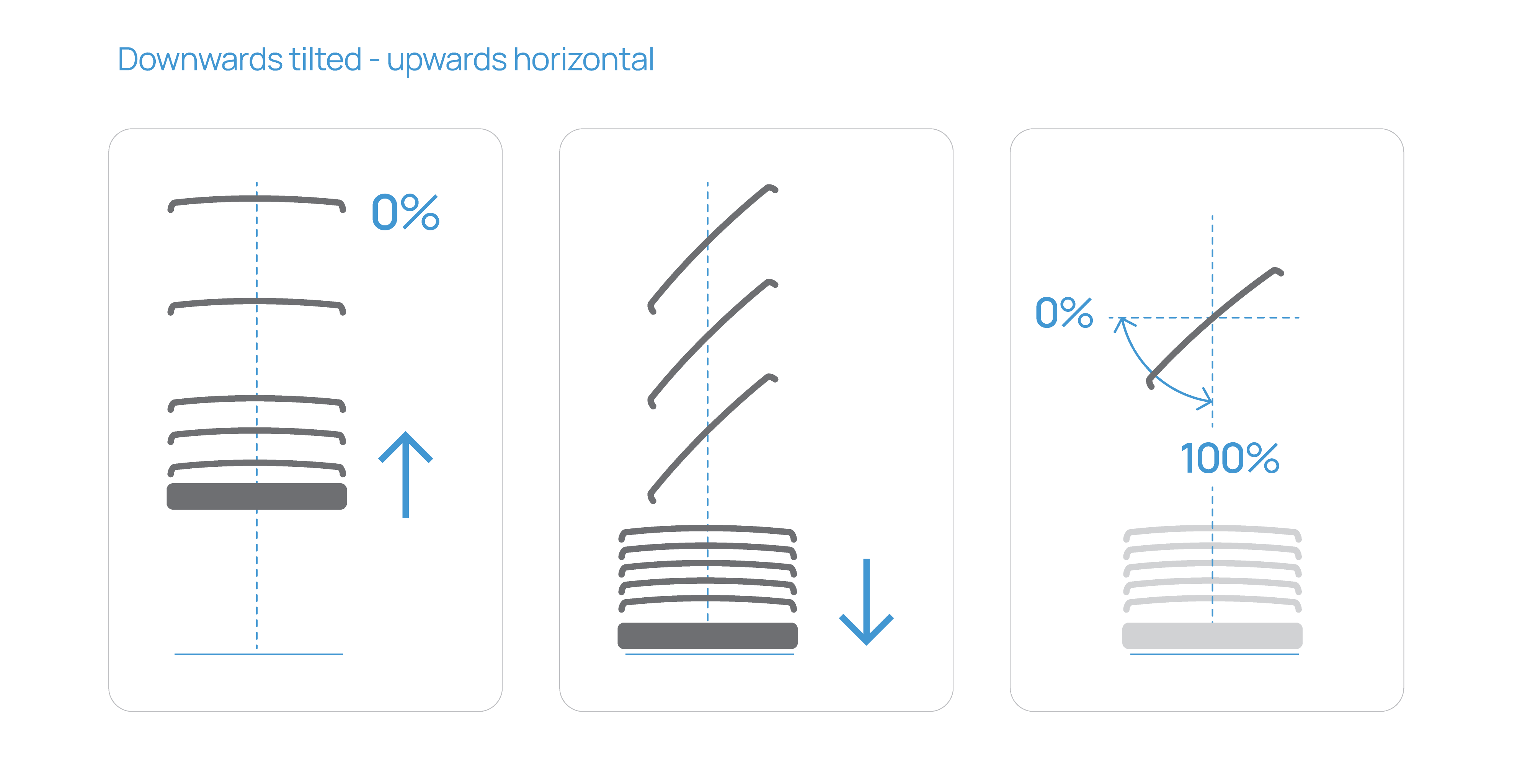
Downwards tilted / Upwards horizontal
In this configuration, “Downwards Tilted” means that when the blind is moving downward, the slats are tilted in a downward direction but not fully closed, allowing limited light to pass through. This provides a balance between shading and daylight rather than full darkening.
To achieve a fully closed position, an additional slat adjustment command (e.g., via the Pause object or Slat Position object) must be issued after the blind has stopped moving.
“Upwards Horizontal” indicates that before the blind begins moving upward, the slats first rotate to a flat, horizontal position—this represents the maximum slat opening, allowing full light entry. Only after reaching this position does the blind start its upward movement. The slats do not rotate beyond horizontal; there is no upward tilt beyond this point.
See Figure 9 for visual representation, illustrating how the 0–100% Slat Position values map to actual slat angles for this type.
-
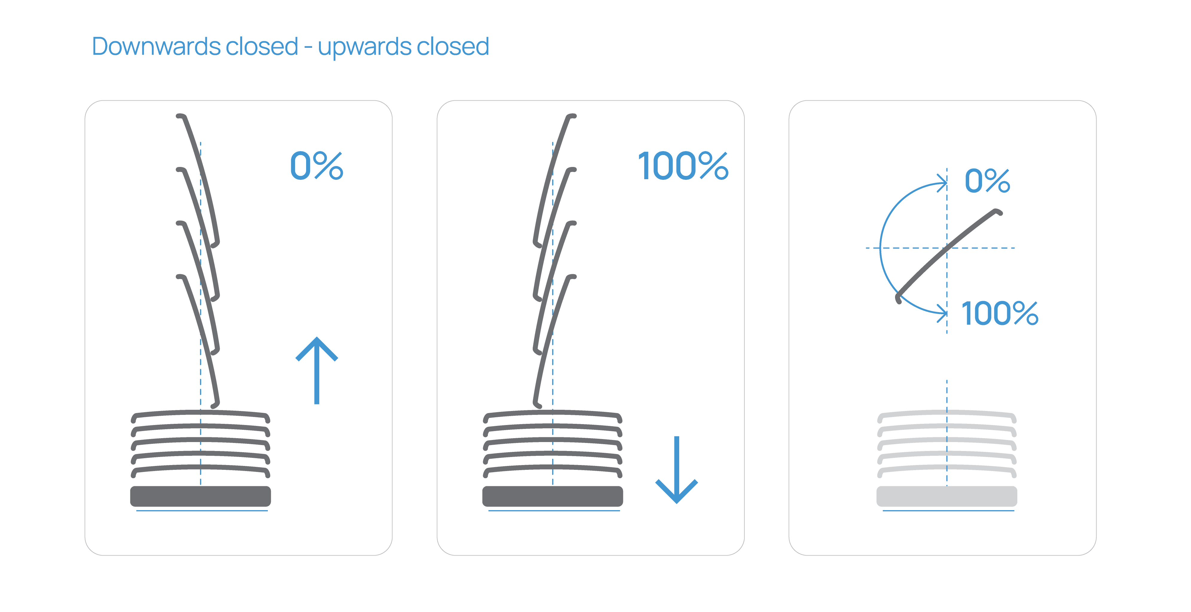
Downwards closed / Upwards closed
In this configuration, the slats can achieve a fully closed position in both movement directions.
“Downwards Closed” means that when the blind is moving downward, the slats are tilted shut in the downward direction, completely blocking light.
“Upwards Closed” indicates that before the blind begins moving upward, the slats first rotate to a fully closed position in the upward direction. This provides maximum shading and privacy from both sides of slat travel. Only after reaching this closed position does the blind start moving upward.
This type is particularly suitable for applications requiring precise light control and complete visual privacy, regardless of blind direction.
See Figure 10 for visual representation, illustrating how the 0–100% Slat Position values map to actual slat angles for this type.
-
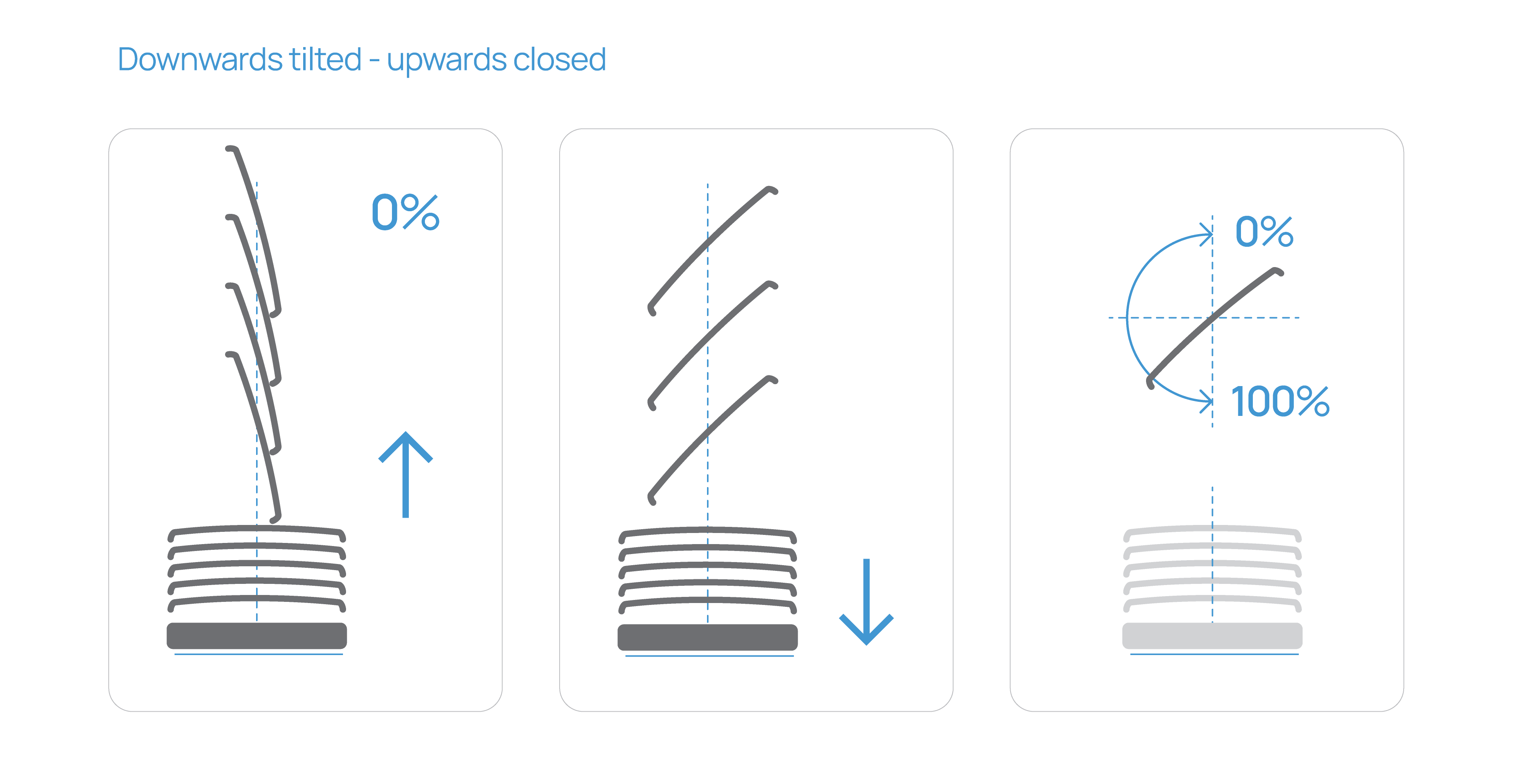
Downwards tilted / Upwards closed
In this configuration, “Downwards Tilted” means that when the blind is moving downward, the slats are tilted in a downward direction but not fully closed, allowing partial light entry while maintaining a degree of shading. To achieve full closure in the downward direction, an additional slat adjustment command is required once the blind has stopped moving.
“Upwards Closed” indicates that before the blind begins moving upward, the slats first rotate to a fully closed position in the upward direction—completely blocking light. Only after reaching this position does the blind start its upward movement.
This type is ideal when complete light blocking is only needed at the upper end of travel, offering a blend of daylight control, shading, and privacy.
See Figure 11 for visual representation, illustrating how the 0–100% Slat Position values map to actual slat angles for this type.
Encoding: 1-byte; DPT 5.001 (percentage)
To add aGroup address to the Slat position object press the Add button. Provide the desired Group address in the newly appeared field and then click on Save button.
You can assign up to three (3) Group Addresses to the Slat position object.
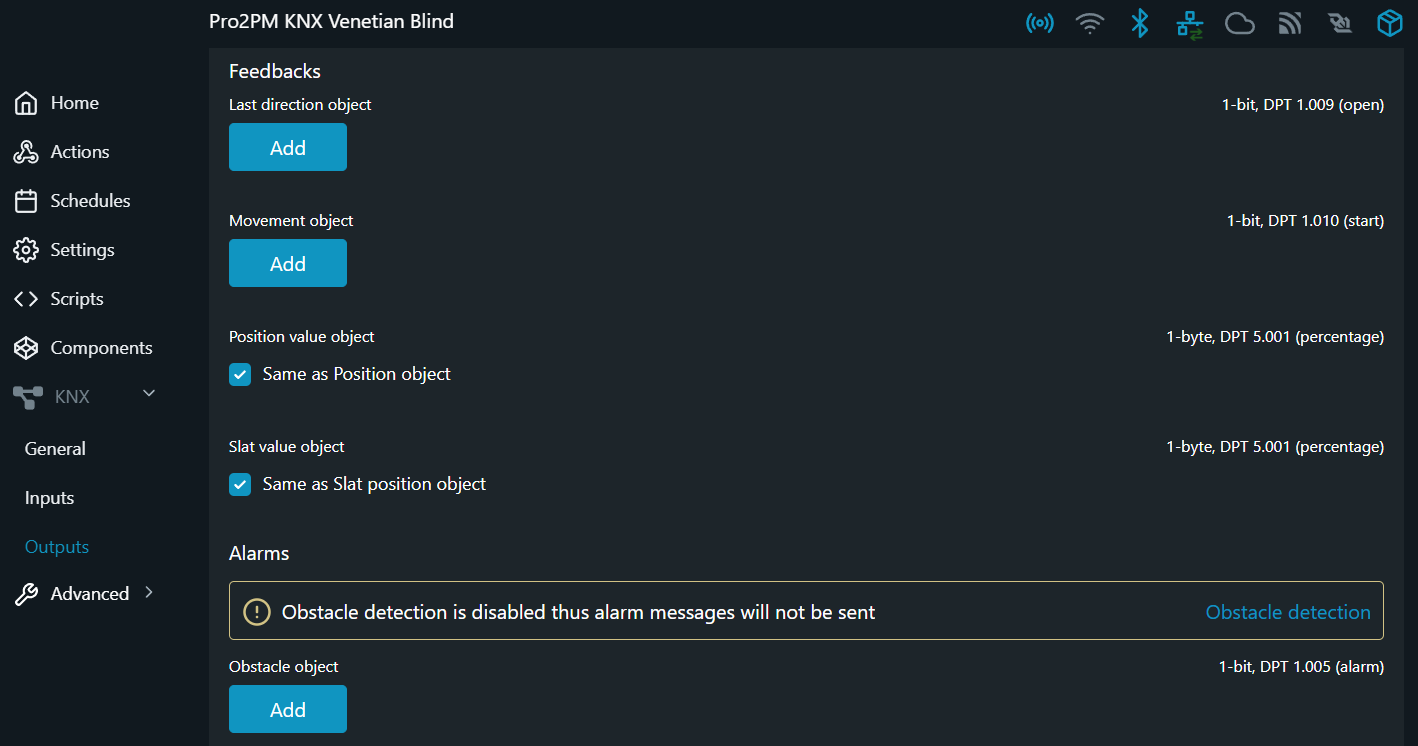
Step 5 - Last direction object
The Last direction object sends the value for the last direction of movement of the cover.
-
When the cover has been moved towards its closing position the value of this object is “1”, and
-
when the cover has been moved towards its opening position the value of this object is “0”.
Encoding: 1-bit; DPT 1.009 (open)
To add aGroup address to the Last direction object press the Add button. Provide the desired Group address in the newly appeared field and then click on Save button.
You can assign only one (1) Group Address to the Last direction object.

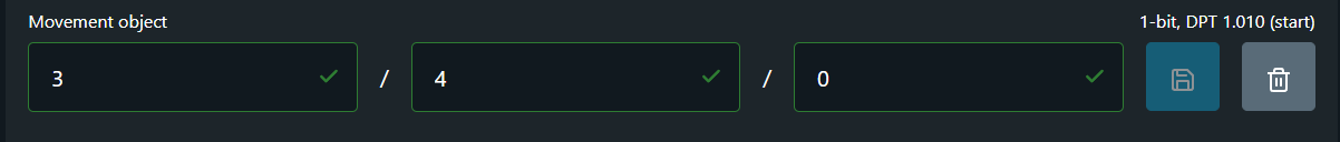
Step 6 - Movement object
The Movement object sends the movement status of the cover. The following information is sent directly:
-
Sends logical “1” when the movement/cover is started, and
-
Sends logical “0” when the movement/cover is stopped.
Encoding: 1-bit; DPT 1.010 (start)
To add aGroup address to the Movement object press the Add button. Provide the desired Group address in the newly appeared field and then click on Save button.
You can assign only one (1) Group Address to the Movement object.
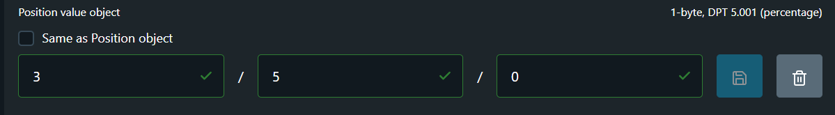
Step 7 - Position value object
The current position of the cover is provided as a value between 0-100%. The corresponding status object Position value object sends the value on the KNX bus if the drive has reached a fixed position after a movement.
Encoding: 1-byte; DPT 5.001 (percentage)
By default the check-box for Same as ... object is active, meaning that the device is going to "write" back the position reached at the Group Address provided in the Position object field.
If you wish to add separate Group Address to the Position value object you should uncheck the check-box Same as ... object and add the desired address in the fields provided below it. To save the new added configuration click on Save button.
You can assign only one (1) Group Address to the Position value object.
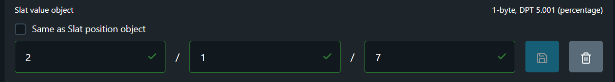
Step 8 - Slat value object
Slat value objectreports the actual percentage value of the current slat position (0–100%), allowing the system or user interface to monitor the true slat angle at any given moment.
The reported value reflects the slat position after the most recent movement or adjustment and accounts for the installed blind type and its slat behavior.
Encoding: 1-byte; DPT 5.001 (percentage)
By default the check-box for Same as ... object is active, meaning that the device is going to "write" back the slat position value at the Group Address provided in the Slat position object field.
If you wish to add separate Group Address for the Slat value object you should uncheck the check-box Same as ... object and add the desired address in the fields provided below it. To save the new added configuration click on Save button.
You can assign only one (1) Group Address to the Slat value object.
Step 9 - Obstacle object
Obstacle detection is safety option provided by Shelly and ensures longevity of any cover (roller or shutter) system. When this feature is enabled it allows the cover to stop or change direction if it encounters an obstacle while driving. More detailed description is provided by this link.
The Obstacle object sends the following information:
-
Sends logical “1” when an obstacle is detected, and
-
Sends logical “0” when no obstacle is detected.
Encoding: 1-bit; DPT 1.005 (alarm)
To add aGroup address to the Movement object press the Add button. Provide the desired Group address in the newly appeared field and then click on Save button.
You can assign only one (1) Group Address to the Obstacle object.
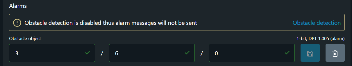
NOTE: If the obstacle detection is not enabled an information panel is displayed above the Group address field.
Until this feature is enabled no alarm messages will be sent at the provided Group address for Obstacle object.