Introduction
Integrating Shelly devices with wireless Shelly BLU sensors is easy and offers expansion options for KNX systems.
A Shelly Wi-Fi device that supports pairing with a Shelly BLU device can use the signals from that sensor to trigger local automation and in turn inform the KNX system of the change.
Prerequisites
Knowledge and understanding of how individual Shelly devices are installed, configured and integrated into automations or Shelly cloud.
Shelly Wi-Fi device with KNX and BTHome components (fw 1.4) support and a Shelly BLU Motion sensor.
Case description
Building floor already equipped with KNX automation system with adjacent staircase where a simple timer based light control was installed. In order to provide similar experience as in the office space and to conform to the electricity savings plan a motion based light needs to be installed.
Existing installation
The drawing shown on Fig. 1 represents part of a building infrastructure - common area of a staircase and connecting to it corridor on a certain floor, all of which is part of a greater office building with several staircases.
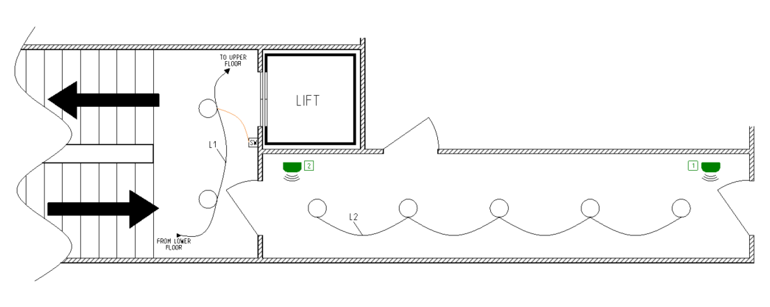
Individual offices and the connecting corridors between them have already been considered as an area with light traffic, so a KNX automation system is used to assure intelligent lighting control. What was not considered is the amount of traffic caused by the visiting customers and office employees, moving between floors. That traffic caused the staircase lighting to stay lit almost all of the time during the operational hours of the building.
Using Table 1 below, we summarize the existing lighting installation shown in Fig. 1 by focusing on a single floor only.
|
Table 1 - Lighting circuits description |
||||
|---|---|---|---|---|
|
Name |
Description |
Wiring |
Activated by |
Control |
|
L1 |
Staircase lighting |
Standard |
Wall switch c/w staircase timing relay |
ON/OFF |
|
L2 |
Corridor lighting |
KNX |
Motion sensors with self timers |
ON/OFF |
Due to the existing KNX automation system and the requested, by the contractor, flawless co-existence and if possible combination of both automation systems, we need to make few clarifications regarding the corridor lighting circuit (L2). The following part and information in it concerns mostly the KNX integrator, who is responsible for the KNX installation. In the case described we have a master-slave dependence of KNX motion sensors due to the fact that two (in this case) of them were used to control the same lighting circuit. In Table 2 we describe that dependence. In case the provided here implementation is to be recreated, we’ll provide extra explanation (provided in column Notes) about the used KNX objects and the Group Addresses they are part of. Such clarification is needed as KNX object names differ from manufacturer to manufacturer.
|
Table 2 - KNX automation system |
||||
|---|---|---|---|---|
|
Num |
Device |
Object name |
Assigned to GA |
Notes |
|
1 |
Master presence detector |
Switch object |
0/0/1 |
Object witch represents that presence/movement is detected by sensor. By using this object the sensor controls the related channel of the switch actuator to turn ON or OFF the lighting circuit |
|
Trigger object |
0/0/2 |
This object is used to trigger the sensor's output via one or more related to the controlled lighting circuit slaves (other sensors) |
||
|
2 |
Slave presence detector |
Switch object |
0/0/2 |
Object witch represents that presence/movement is detected by sensor. |
|
3 |
Switch actuator, channel X |
Switch object |
0/0/1 |
Switches ON/OFF the corridor lights (L2). |
|
Feedback object |
N/A |
Optional. Not used in current case. |
||
Optimized installation
In order to reduce the electricity costs further more, we suggested to equip all of the common areas on all staircases with easy to install motion sensors and separate switching control gear. By doing so we achieve separate triggering of the lights only where an actual movement occurs, instead of triggering all of the staircase lighting by wall mounted switches, since in the existing electrical installation they are wired as one electrical circuit. This may sound difficult to accomplish, but actually it requires no additional wires to be installed and minimum wiring labor on the existing installation only.
Fig. 2 below shows the solution described above, again the installation is for a single floor.
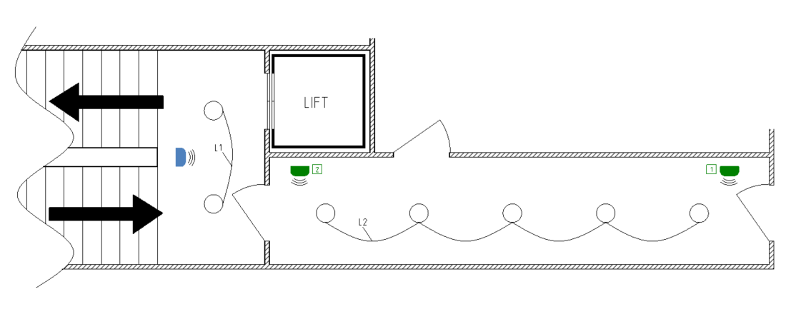
In comparison with the drawing shown on Fig. 1 we see that lighting circuit L1 is no longer connected through floors and the latter have become with an individual switching control provided by Shelly Mini 1 smart relay (not shown), which easily fits inside (or next to) any ceiling mounted lights. In addition we added Shelly BLU Motion sensor (shown in blue color). See in Table 3 which devices were added and which were removed.
|
Table 3 - manipulations on staircase lighting circuit, L1 |
||
|---|---|---|
|
Device |
Function |
Add/Remove |
|
Staircase timer |
Energizes L1 on all floors; Off delay timer |
Existing; to be removed |
|
Wall switch /per floor/ |
Trigger input of staircase timer |
Existing; to be removed |
|
Shelly Mini 1 |
Energizes L1; BLE Gateway |
New; to be added |
|
Shelly BLU Motion |
Motion detector; Off delay timer |
New; to be added |
Electrical installations are not part of this guide. Proper installation and all involved electrical connections are an absolute must not only to assure proper operation, but also to provide safety operation and user protection. All of the required operations must be preformed by an experienced technician according to the provided documentation.
Configuration
Shelly BLU Motion sensor is Bluetooth Low Energy (BLE) wireless device, which needs a dedicated gateway to receive the data being sent from it.
Shelly Mini 1 is a remote controlled relay, which incorporates a variety of communication protocols. Out of the obvious switching control function, Mini 1 also supports BTHome and KNXnet/IP communication protocols. Therefore we will use it as an intermediate device between the newly installed motion sensor and the existing KNX installation.
Due to the integration of two independent automation systems into one, we split the configuration process into two steps.
Shelly Mini and Shelly BLU Motion pairing
Enable Bluetooth
As Bluetooth gateway we use Shelly Mini 1 and we have to enable the Bluetooth gateway function on it. To do that open device’s embedded web interface by navigating to http://192.168.33.1 or if the device is part of another network go to http://<device ip> and then navigate to Settings → Bluetooth.
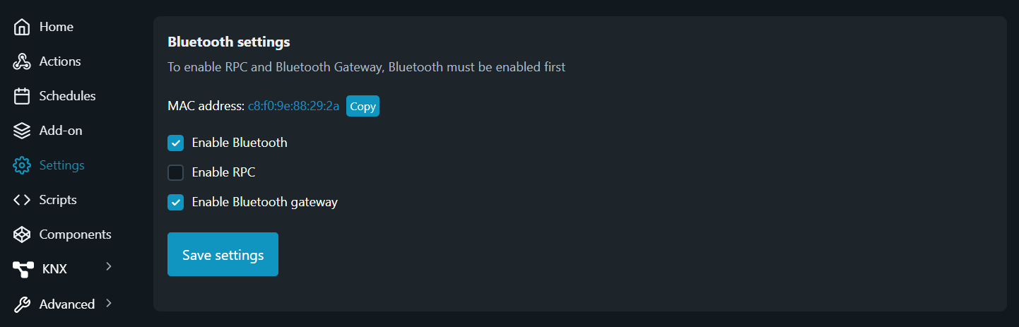
Click on the check-box “Enable Bluetooth” to turn Bluetooth radio on. Once the radio is switched on the check-box “Enable Bluetooth gateway” becomes also active any may be toggled. Click on it to enable it and then press on “Save settings” for saving the configuration changes.
Add device
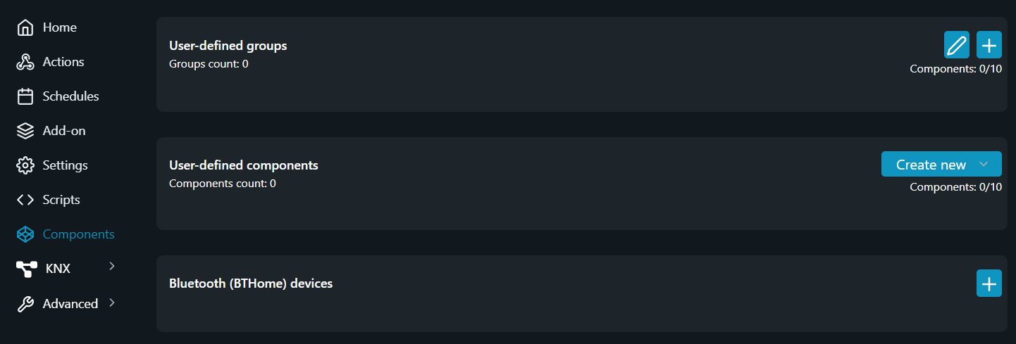
Once the Bluetooth radio is on and the gateway function enabled we need to add the device(s) we want to use. In our case this is Shelly’s BLU Motion sensor. For integrating external devices we need to add them as separate Components. Follow the step below to add a BLE device.
From the embedded web interface navigate to Components and click on Plus icon at the Bluetooth (BTHome) devices field.
Then you should scan for nearby Bluetooth available devices. Click on the Scan button on the newly appeared window, locate the Shelly BLU Motion (in case more than one Bluetooth device exists nearby) and follow the instructions to add it.
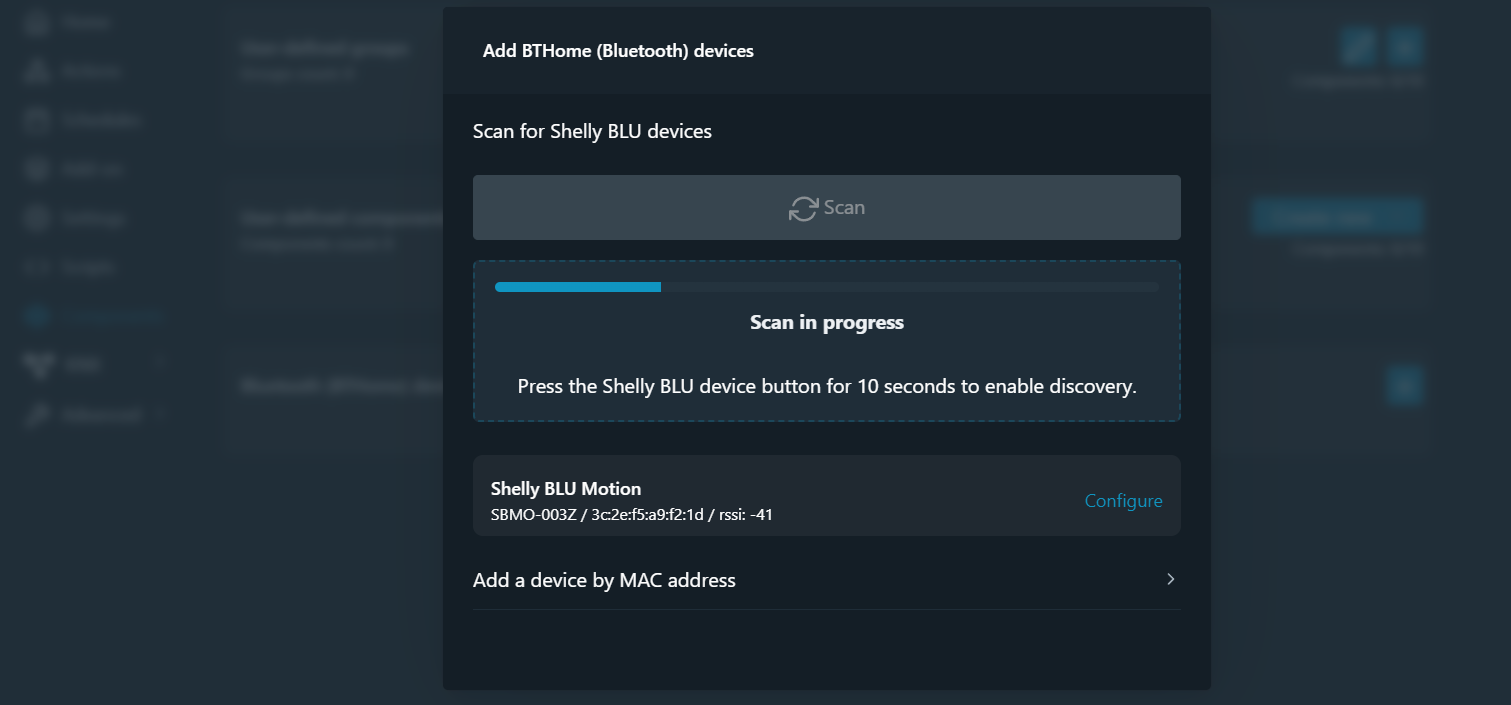
After the device is discovered click on Configure and follow the steps on the screen to to add your new device.
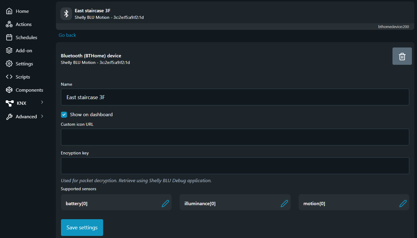
The default setup of the device requires only for the field Name to be entered. Specify a device name which is easy for follow up use. In our case we give a name based on the device location, which here is “East staircase 3F”.
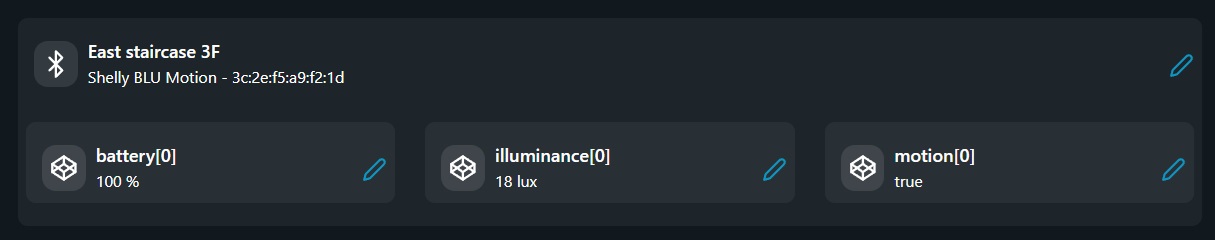
By selecting or dissecting the check-box Show on dashboard the user may define if the data of the Supported sensors to be displayed on the Home page of the embedded web interface.
To save the changes you’ve made scroll down and click on Save settings button.
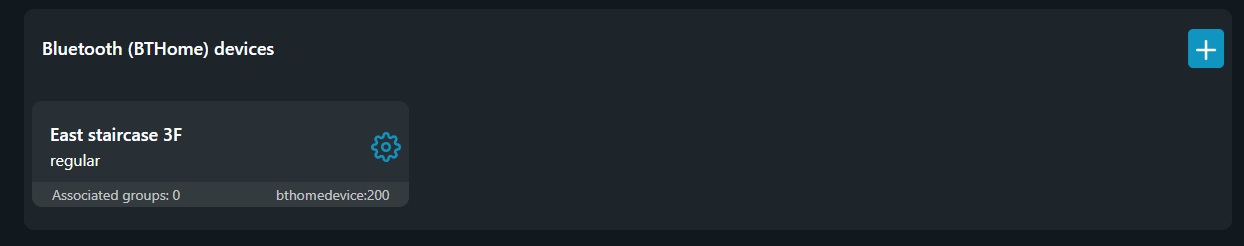
Upon competition you should get your device listed and the embedded web interface should look something similar to the picture shown below.
Add Actions
Once we have completed the pairing procedure we need to define an action based on the sensor input. The easiest and simplest way to do that is by creating separate event actions - one for each condition we need, since every action may process a single IF-THEN operator only.
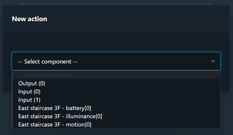
To create a new action we have to click on the Create Action button at the Actions tab in the device’s embedded web interface.
The New action windows appears on screen and as Pic. 7 shows, the Select component drop down menu now contains the information delivered from the newly added Shelly BLU Motion sensor.
For the purpose of this case we need energize the output of Shelly 1 Mini smart replay when a movement is detected and to de-energize it after a certain time when movement is no longer present have elapsed.
Shelly BLU Motion is a Bluetooth device only and configuration of its parameters, like sensitivity and movement time delay, can be made from Shelly Smart Control app.
For configuration of other manufacturers sensors, please coordinate with provided by them documentation.
Therefore we need two IF-THEN operators, one for each boolean statement (true or false) provided by the physical motion interface - last option shown on Pic. 7 - “East staircase 3F - motion[0]”. And since every action may contain one IF-THEN operator only, we need to create two actions.
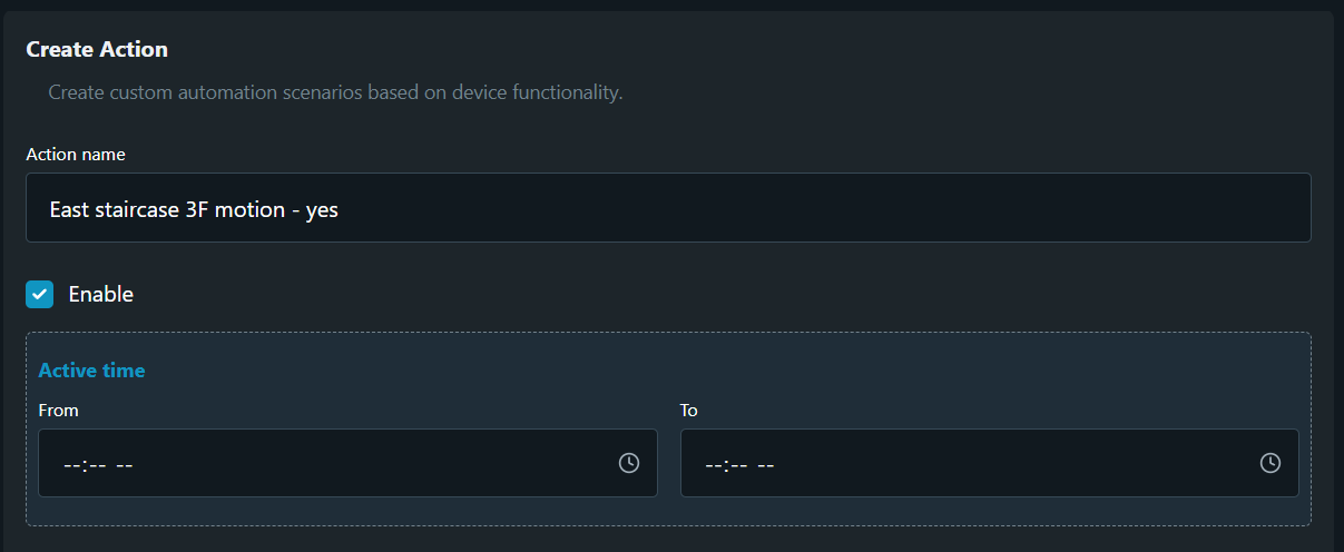
Below we guide you on how to create the first action step-by-step. Every action requires following minimum of data to be entered:
-
Action name - use clearly defined action names, especially when using many actions. See Pic. 8a.
-
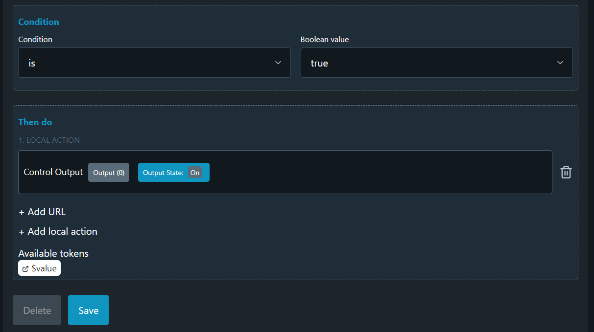
Condition - define the IF condition of your action case, e.g. “motion[0] is…”.
-
Boolean value - select the desired True/False statement of the Condition, e.g. “… true”.
-
Then do - define the outcome logic output (THEN operator), e.g. Control Output (0) → On”.
All of the above steps are shown in Pic. 8a and Pic. 8b below.
Similar Action have to be created to de-energize the Output (0) when movement is no longer present. Repeat the steps above to create another Action reversing the logic of the one shown on Pic. 8a and Pic. 8b. Upon successful completion of the task you should have you two actions created and looking like Pic. 9.
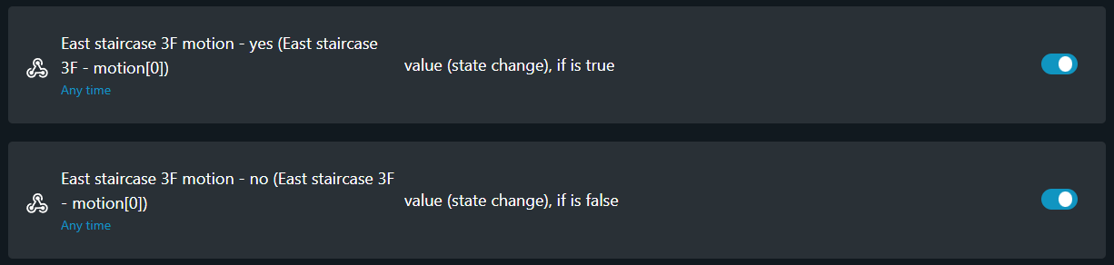
With the Toggle switches shown on Pic. 9 every action operation may be Enabled or Disabled.
Once the Shelly BLU Motion and Shelly Mini 1 have been paired and the control Actions created the staircase lighting has its own autonomous operation. The following KNXnet/IP integration is provided only to expand the capabilities of both autonomous systems.
KNXnet/IP
With the current case we tend to show two different integrations of Shelly devices into KNX network infrastructure. The first option is suitable for lower floors of the building, where the movement direction is mostly occurring through the stairs, without using the corridor leading to the offices. And the second option may be implemented for the higher floors of the building, where the most of traffic is due to using the lift and offices connecting corridor. Now let’s first deal with the common KNX settings and then we will explain each option individually.
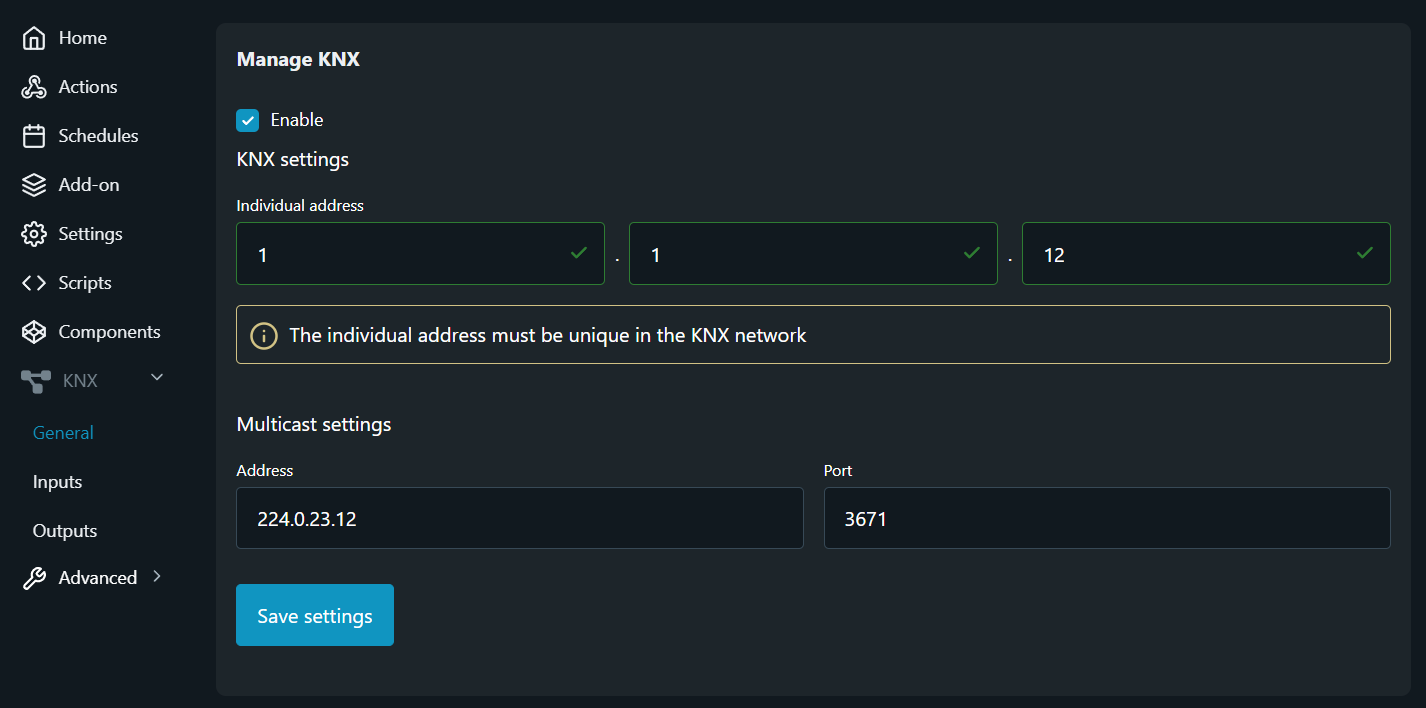
General settings
Coordinate with the KNX system integrator of the building in order to assign a new KNX Individual address for newly added Shelly Mini 1 and to get the Multicast communication settings of the network.
Once you gather the necessary information open the embedded web interface of Shelly Mini 1 and navigate to the KNX tab.
The firs step is to enable the KNX communication of the device by clicking on Enable check-box and then Save settings button. A device restart is required afterwards. Once the device is restarted navigate back to the KNX tab and enter the settings provided to you by the KNX integrator and again press the Save settings button. By accomplishing the task your embedded web interface should glook something like the picture shown on Pic. 10.
For the described use case we don’t use device’s Inputs, therefore no setup is needed for them. With this said let’s continue with the Output setup. and review the two different integrations we already mentioned above.
Outputs
In order to make the KNX configuration of the Output of Shelly Mini 1 smart relay and its issue-free interaction with the existing KNX network, we need to take another look at Fig. 2 and better understand the data provided in Table 2, which describes the Master-Slave relation between the installed KNX motion detectors. According to that data we understand that the Master KNX sensor, marked with 1 on Fig. 2, is installed at far right corner of the corridor and the KNX sensor operating in Slave mode is the one near to the staircase common area, where Shelly devices are installed. Having this information provided let’s proceed with the KNX configuration based on the already described sub-cases.
Lower floors integrations
As we have already mentioned at lower floors of the building, the common staircases area is used by people passing from floor to floor. Therefore we need to energize the Output of Shelly Mini 1 smart relay when Shelly BLU Motion sensor detects movement only. And in the same time if we desire to represent this lighting status change back to the KNX network (by using the Feedback object), we need to provide it in such a way that avoids energizing of the common corridor area. A case that would occur if we use the current Group address (0/0/1) serving that role, due to the "write" flag of the status object. So to achieve that we need to fill the Table 2 with an additional Group address - 0/0/3, which have to be coordinated with the KNX integrator too. In the current case we don’t need to energize the staircase’s common area by KNX network, so we don’t need to provide a Group address for the Switch object. Then here is how the Output KNX settings would look like (Pic. 11).
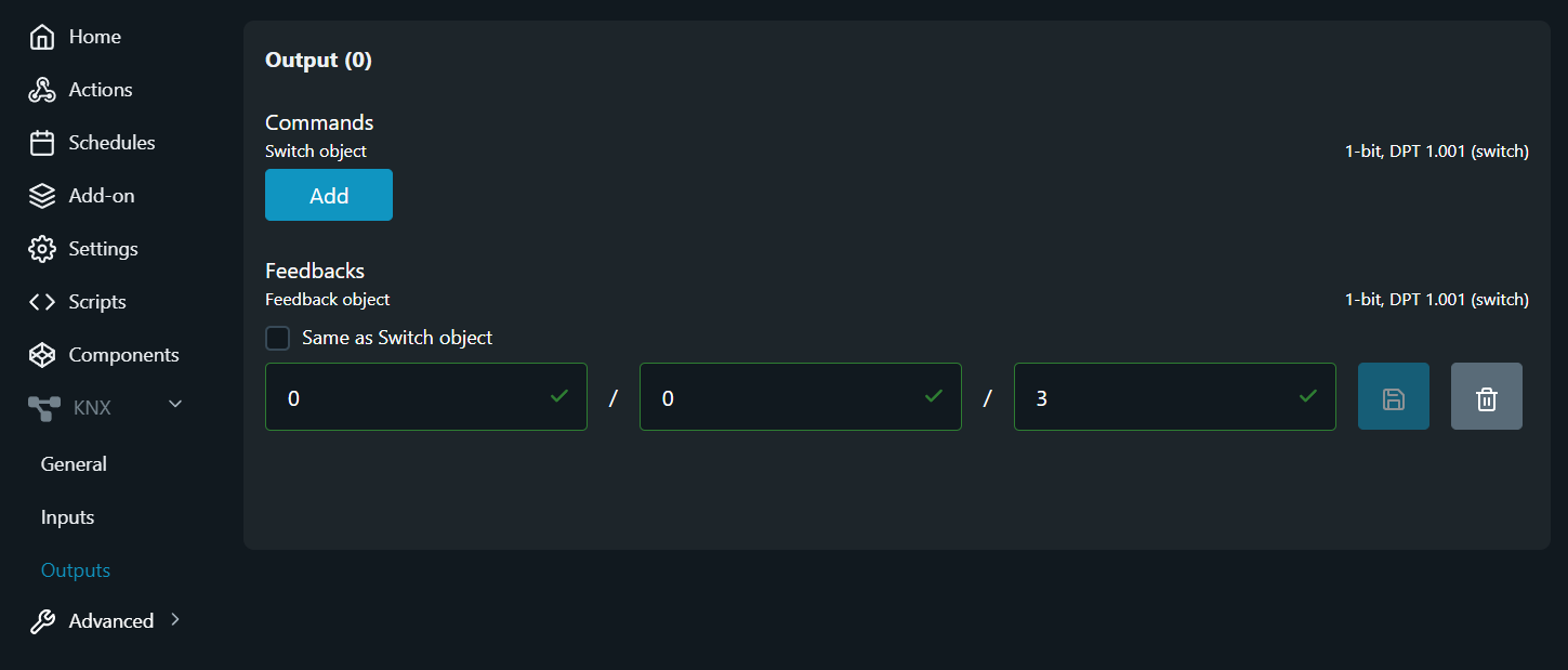
Feedback object settings
Upper floors integrations
In the building’s upper floors it is good to also provide the ability to energize the staircase common area by the Slave KNX sensor (marked with No. 2 on Fig. 2) and vice-versa. By doing so we provide a bi-directional switching of the lights in the staircase’s common area when the Slave KNX sensor is approached and also we can turn on the lights of the connecting corridor when movement is detected by Shelly BLU Motion detector.
To achieve this with Shelly Mini 1 smart relay we have to represent it to the KNX network as another Slave. We can do that without making any changes of the configuration settings made so far. All we need to do is to assign the Group address in which the Master trigger object is located (see Table 2) for both Switch object and Feedback object - 0/0/2. By doing such setup we redirect the command received by Shelly BLU Motion sensor via the Feedback object of Shelly Mini 1 to the Master KNX sensor, which energizes the corridor lights and also by listening onto the same Group address using the Switch object we "catch" the switching command that is being sent from the Slave KNX sensor. The easiest way to do such setup is by using “Same as Switch object” check-box option provided for Feedback object, all of which is shown on Pic. 12 below.
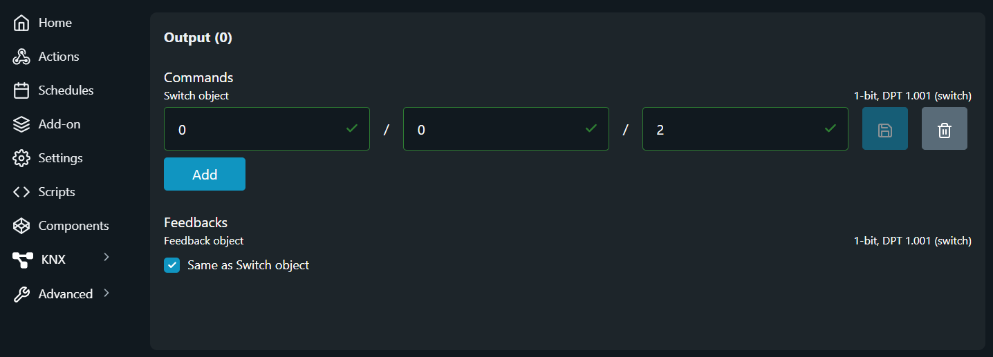
Switch object and for Feedback object.
Conclusion
The current use case describes how a successful communication may be established between any Bluetooth Low Energy devices and KNX devices by using Shelly Mini 1 smart relay (or any Shelly device with the support of Bluetooth Gateway) as intermediate device.