Introduction
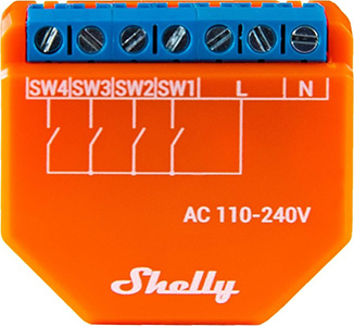
Shelly I4 is a four inputs smart Wi-Fi device which allows for easy retrofitting of existing spaces.
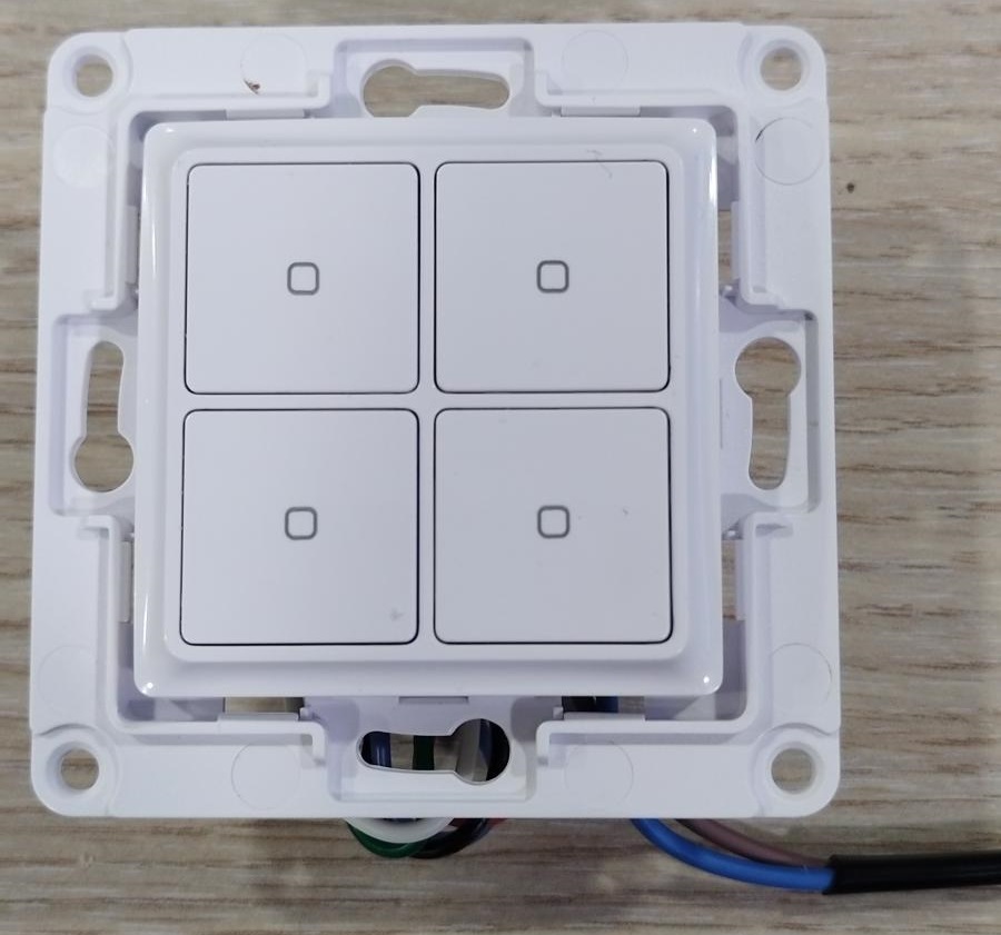
Sample assembly of Shelly’s Wall Switch 4 and Plus i4 which may be used for retrofit installations and for new installations alike.
|
|
|---|
Assembly
|
Shelly Wall Switch 4 |
Shelly Plus i4 |
|---|---|
|
Button 1 (Top Left button) |
Input 0 (SW1 terminal) |
|
Button 2 (Top Right button) |
Input 1 (SW2 terminal) |
|
Button 3 (Bottom Left button) |
Input 2 (SW3 terminal) |
|
Button 4 (Bottom Right button) |
Input 3 (SW4 terminal) |
Case description
The following use case may be used when expanding an office to a larger area.
Let’s assume that Company A, which is using Office A needs to expand it’s area space and have bought the office next to it (Office B). Prior to that both offices have had an independent control of their lighting circuits which now have to be joined in one common control. Further to that Office A is using smart lighting control system done with KNX equipment and Office B is using standard electrical wiring. Major difference between the two control methods is how wiring is organized.
Existing installation
Lighting control diagram of existing electrical installations in both offices is shown on Fig. 1.
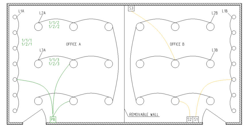
Distribution boards are not shown.
With green color is shown the KNX means of control and Group addresses used to achieve it. Yellow color represents the control of standard electrical installation.
|
Legend Office A |
||||
|---|---|---|---|---|
|
Name |
Description |
Wiring installation |
Control |
Group address |
|
L1A |
Lighting circuit 1 |
KNX |
4-fold PB / Btn 1 |
1/1/1 & 1/2/1 |
|
L2A |
Lighting circuit 2 |
KNX |
4-fold PB / Btn 2 |
1/1/2 & 1/2/2 |
|
L3A |
Lighting circuit 3 |
KNX |
4-fold PB / Btn 3 |
1/1/3 & 1/2/3 |
|
L1A, L2A, L3A |
All circuits OFF |
KNX |
4-fold PB / Btn 4 |
0/0/1 |
|
Legend Office B |
|||
|---|---|---|---|
|
Name |
Description |
Wiring installation |
Control |
|
L1B |
Lighting circuit 1 |
Standard |
Wall switch S1 |
|
L2B |
Lighting circuit 2 |
Standard |
Wall switch S2 |
|
L3B |
Lighting circuit 3 |
Standard |
Wall switch S3 |
New installation
Once acquiring the additional space of Office B, Company A wants to control all lighting circuits seemingly like it was before the expansion. KNX installation provides that ease and central control for a significant cost - special wiring and expensive devices.
As mentioned above KNX require special wiring where all means of control are concentrated in the distribution board opposing to the standard electrical installation where the control method is processed from within the installed wall switch. Such difference in electrical installations makes the migration to KNX quite expensive not only because of the high cost of KNX devices, but also due to the requirement of rearranging the electrical wiring too.
Shelly devices are designed in mind to provide ease of installation in almost any case may arise, which makes them perfect for use in this case.
The drawing below shows what we can achieve by simply adding Shelly devices and no additional wiring!
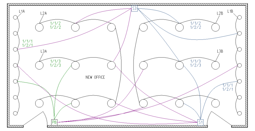
In the drawing the blue color shows Shelly means of control using KNX integration. Due to using the same KNX Group addresses already programmed for the existing installation in Office A we achieve full control of all lighting circuits in the room, that is shown with purple.
Shelly + KNX settings
The table below assumes a wide spread case of lighting circuits with implemented protection according to residential/commercial building requirements worldwide. For Europe such circuits are commonly protected by 6A to 10A Type B MCBs or 6A to 10A/30mA RCBOs (MCB Type B and RCD Type A or AC). Prior to any installation check the load of every lighting circuit and confirm it fits the specifications of the chosen Shelly device.
|
New equipment |
||
|---|---|---|
|
Name |
Description |
Control device |
|
L1A |
Lighting circuit 1A |
Use existing |
|
L2A |
Lighting circuit 2A |
Use existing |
|
L3A |
Lighting circuit 13 |
Use existing |
|
PB |
KNX push button |
Use existing |
|
L1B |
Lighting circuit 1B |
Shelly 1 Gen3 , Shelly 1PM Gen3 , Shelly Mini 1 Gen3 , Shelly Mini 1PM Gen3 |
|
L2B |
Lighting circuit 2B |
Shelly 1 Gen3 , Shelly 1PM Gen3 , Shelly Mini 1 Gen3 , Shelly Mini 1PM Gen3 |
|
L3B |
Lighting circuit 3B |
Shelly 1 Gen3 , Shelly 1PM Gen3 , Shelly Mini 1 Gen3 , Shelly Mini 1PM Gen3 |
|
S1 |
Wall switch 1 |
Shelly i4 Gen3 c/w Wall Switch 4 |
|
S2 |
Wall switch 2 |
Canceled |
|
S3 |
Wall switch 3 |
Shelly i4 Gen3 c/w Wall Switch 4 |
As the table above describes the standard wall switches S1 and S3 shall be replaced with Shelly i4 Gen3 devices combined with Shelly Wall Switch 4 - combination of devices which perfectly fit into the existing wall boxes. This installation provides four control buttons in each wall box and saves space. Wall switch S2 is not needed and is canceled (closed).
Additionally we need extra three smart relays for controlling the three existing lighting circuits - L1B, L2B and L3B. For this example we choose Shelly 1 Gen3 which provides everything needed to fulfil these requirements and it can be installed next to the first light bulb / led lamp for each lighting circuit. In case monitoring of power consumption is needed Shelly 1PM Gen3 would be used instead of Shelly 1 Gen3 . Other possible selections are also listed in the table above.
Taking into account the installer is familiar with the detailed information provided from Shelly Knowledge Base regarding KNX configuration of our devices a short set up description regarding means of control follows.
On Fig. 1 we can see the Group addresses (shown in green) which are used in the existing KNX installation to control each lighting circuit individually of Office A. On the first row is shown the Group address assigned to the Switch object (switches ON/OFF) and the second row shows the Group address assigned to the Feedback object. This information may also be found in table “Legend of Office A”.
To achieve desired task we need to combine lighting circuits of Office A with those of Office B in order to remain with the same number of lighting circuits (three). A combination like this give us the ability to control all lights in the office from all three locations in the it.
Fig. 2 shows in blue color the KNX Group addresses we need to assign to the newly added Shelly devices. Following the information provided in it let’s proceed.
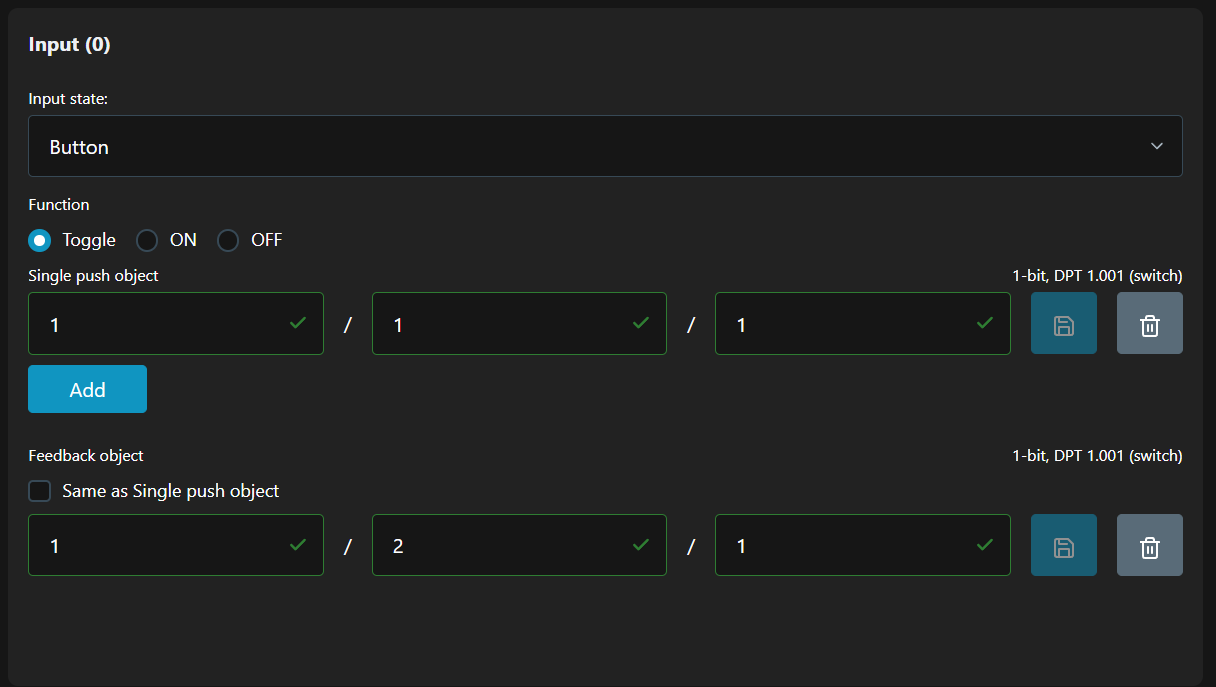
Input 0, Input 1 and Input 2 are sharing the same KNX settings for Input state and operation Function, which are shown below:
-
Input state- Button -
Function- Toggle
Shelly i4 Gen3 Input 0 settings
Input 0 is energized from the top left button of both Shelly Wall Switch 4 units in the room. We will use it to control both lighting circuits L1A & L1B together. To do that we need to assign the following Group address:
-
Single push object- GA 1/1/1, with which both the KNX switching actuator and the Shelly smart relay are energized/de-energized. -
Feedback object- GA 1/2/1, which represents the current state of the control relays.
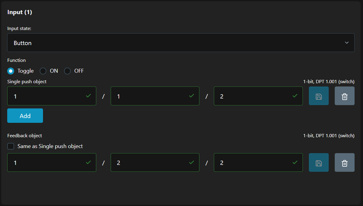
Shelly i4 Gen3 Input 1 settings
Input 1 is energized from the top right button of both Shelly Wall Switch 4 units in the room. With this button we will control L2A & L2B together. Bellow are the Group addresses we need:
-
Single push object- GA 1/1/2 -
Feedback object- GA 1/2/2
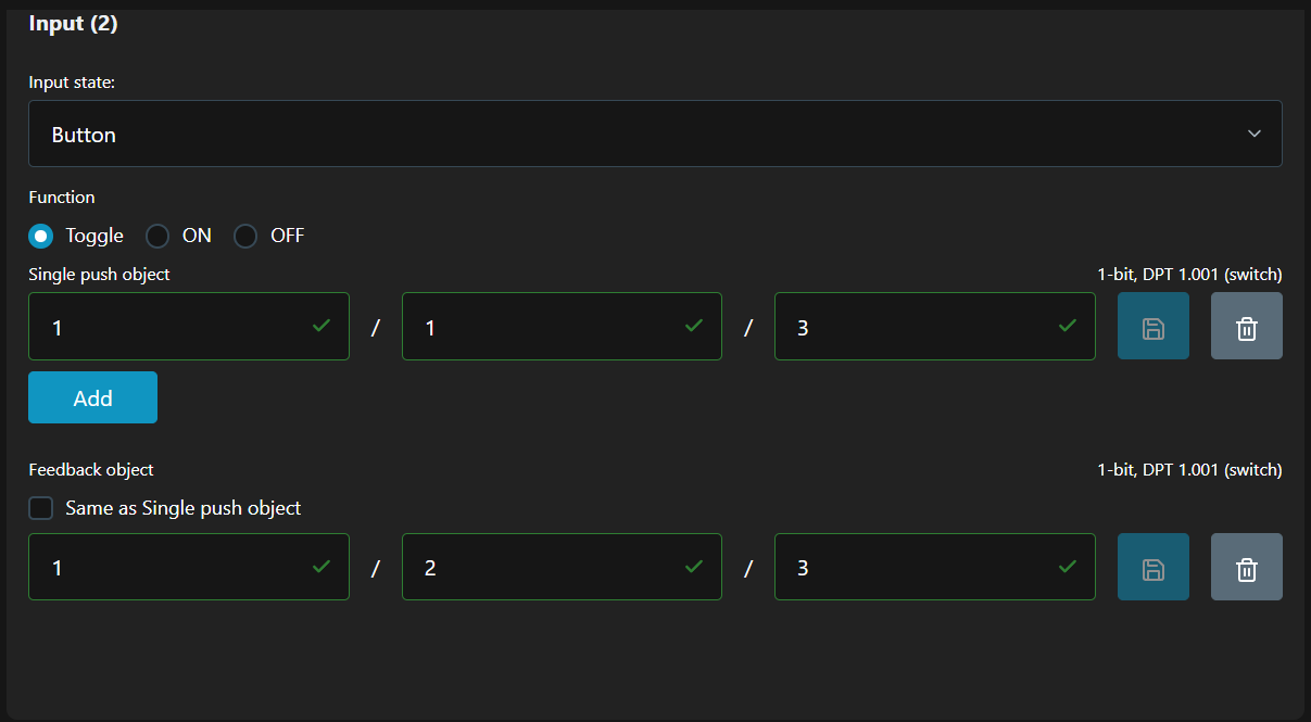
Shelly i4 Gen3 Input 2 settings
Input 2 is energized from the bottom left button of both Shelly Wall Switch 4 units in the room. With this button we will control L3A & L3B together. Bellow are the Group addresses we need:
-
Single push object- GA 1/1/3 -
Feedback object- GA 1/2/3
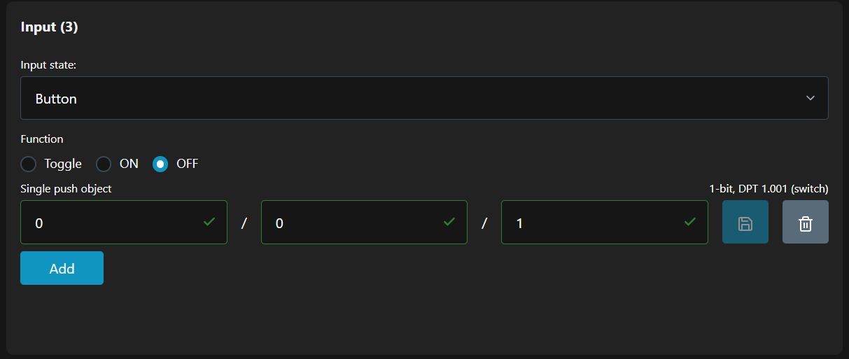
Shelly i4 Gen3 Input 3 settings
Input 3 is energized from the bottom right button of both Shelly Wall Switch 4 units in the room. We want to use this button as Master control switch sending an OFF command, a.k.a. ‘Master OFF’ to all lighting circuits in the room. In order to achieve this we need to change the operating Function of the button, while keeping the same Input state
-
Input state- Button -
Function- OFF, which means with every press of the button an OFF telegram will be sent on the KNX network to the specifiedGroup address.
Once the OFF Function is selected the Feedback object is not needed anymore, hence is not shown.
Common practice for KNX integrators is to define a separate Group address for Master OFF function in which all command objects are gathered. As we can see in the table Legend Office A the Group address for this is 0/0/1.
-
Single push object- GA 0/0/1
All of the settings above have to be done on both (in our case) Shelly i4 Gen3 devices placed in S1 and S3.
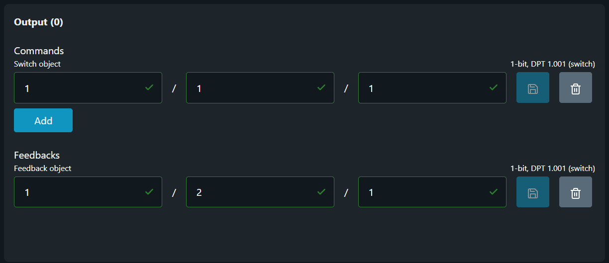
Shelly 1 Gen3 Output 0 settings
Shelly 1 Gen3 devices are installed in a way to interrupt and pass through them the direct wiring coming from the switch to the first light of the lighting circuit. Bellow are shown the KNX settings we need to implement for all three lighting circuits, i.e. in all three Shelly 1 Gen3 devices.
-
For L1B lighting circuit
Switch object- GA 1/1/1
Feedback object- GA 1/2/1 -
For L2B lighting circuit
Switch object- GA 1/1/2
Feedback object- GA 1/2/2 -
For L3B lighting circuit
Switch object- GA 1/1/3
Feedback object- GA 1/2/3
Conclusion
Once all of the configuration above is done it will automatically delegate the control of all newly added Shelly devices to the KNX push button (shown as PB in Fig. 1 and Fig. 2), hence all three buttons in the new office space will be sharing the same button functions.
Although we have achieved the operation we need there is another benefit we gained too. If we need to further separate the room into two offices once again we don’t need neither to rewire, nor to add/remove any devices for separating the lighting circuits! All we need to do is to change the Group addresses with which lighting circuits are controlled.