Inputs
Shelly devices with inputs and outputs have by default an input associated with an output. When using device inputs for integration into a KNX system the recommendation is to de-associate the input from the output and continue with the recommended configuration method below.
In case the pair of input and output can not be unlinked keep in mind that the internal to the Shelly device logic and the logic implemented with the KNX integration will be executed in parallel and some of the resulting effects will not be traceable in the KNX system.
Every input represented into KNX as an input object (i.e. Switch or Button) inherit the following KNX access flags:
-
read - other KNX devices sharing the same Group Address may read from object only
-
transmit - ability to transmit input’s state upon every status change to the KNX network
Input state defines the operating mode in which this Input shall be used.
If the selected Input state is incompatible with the one defined in Input/Output settings a notification stating "Selected mode is not supported by the current input type” appears. Either change the Input state in KNX settings or go back to the Input/Output settings and choose compatible settings.
In the right side of every Group address field two buttons are available - Save and Delete, giving you the option either to save or delete the entered configuration.
Keep in mind that entered Group addresses must share the same DPT type. Shelly Web UI can not check that!
Up to three Group addresses may be added for every command object, which represents an input. These command objects inherit the access flags mentioned above.
Each Group address assigned represents separate command object, meaning that it has its Sending attribute always Enabled, a.k.a. Sending Group Address!
The Group Address assigned to Feedback object is used to “read” the current state of the controlled actuator group, i.e. ON or OFF.
Only one Group address may be assigned to Feedback object.
How to configure an Input to be detached from an Output
To limit side effect of internal to the Shelly device logic conflicting with the KNX programmed logic this is the recommended mode of operation.
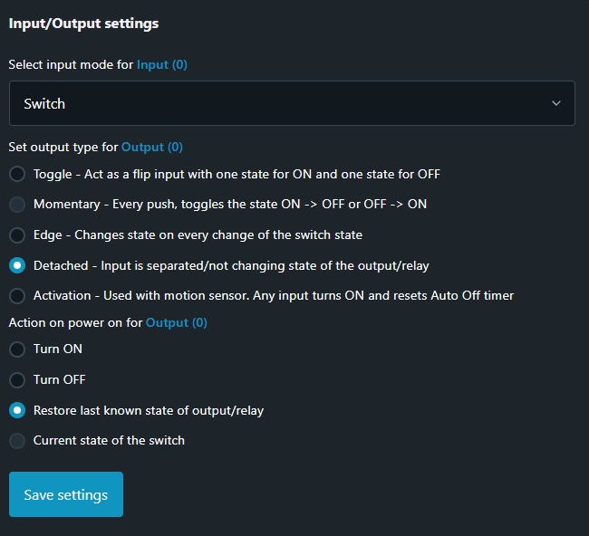
Navigate to the Output configuration, Input/Output settings and select the Detached option
When the selection made for input mode in Input/Output settings differs from the one made for Input state in KNX/Inputs settings tab the following notification is displayed
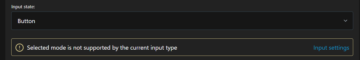
If the message “Selected mode is not supported by the current input type” is displayed the selected KNX function will not be active.
Input mode - Switch
This mode should be used when the Shelly Input has a two-pole stable switch connected to it. From KNX perspective this mode offers limited options. It is recommended to be used as a two positions switching input or similar.
Inputs set in Switch mode may be used as Door/Window event monitor.
Step 1 - Input state
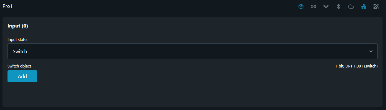
Navigate to the KNX configuration and select Inputs. From Input state drop-down menu select Switch.
Step 2 - Switch object
Add the Group Address to the Switch object, then click 'Save' button.
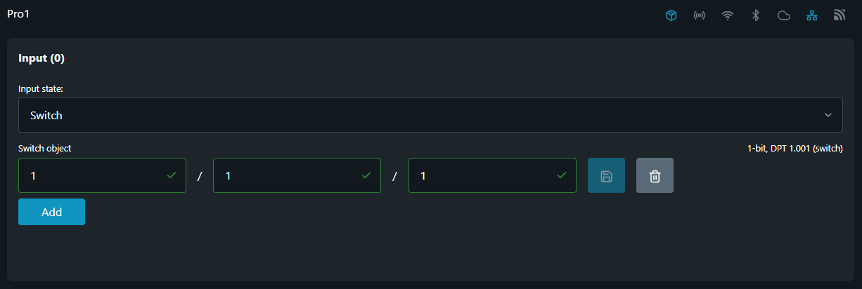
The Switch object represents the current state of the input - energized or de-energized. Therefore the data it will transmit is either "1" (energized) or "0" (de-energized) according to the state of the wired switch.
Encoding: 1-bit; DPT 1.001 (switching)
Input mode - Button
This mode should be used when the Shelly Input has a push button connected to it.
When an input is configured as a Button the full KNX potential of Shelly’s input is available.
Step 1 - Input state
Navigate to the KNX configuration and select Inputs. From Input state drop-down menu select Button.
Input state defines the operation mode in which this Input shall be used.
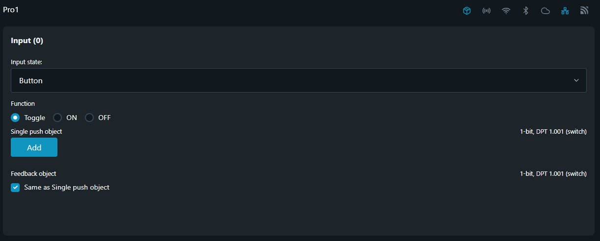
Step 2 - Function
TOGGLE
Toggle is a function which first reads the current state of the controlled actuator group via the group address assigned to the Feedback object and then sends an inverted value with each push-button action, i. e. a "0" becomes a "1", and when the same key is pushed again, a "1" becomes a "0". The device is therefore switched on and off alternately.
ON / OFF
In this mode the input is not consulting the actuator group of it’s current state. The input which always sends the selected function, i.e. ON or OFF, with every activation of the input.
The Function field is used to define Button’s control type and the information to be sent via Single push object.
Step 3 - Single push object
Add the Group Address to the Single push object as shown in the picture, then click Save button.
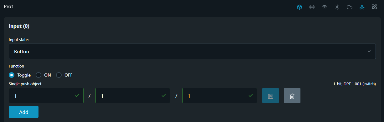
Encoding: 1-bit; DPT 1.001 (switching)
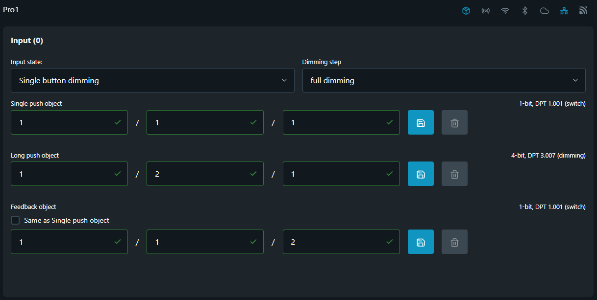
Step 4 - Feedback object
When setting up Feedback object by default the check-box for Same as ... object is active, meaning that the device is going to "read" the state of the controlled actuator group at the Group Address provided in the Single push object field. In case this group does not contain any objects providing feedback status the TOGGLE Function won't work! To avoid such scenario you should uncheck Same as ... object box and enter the Group Address that contain this information in the provided field.
Add the Group Address to the Feedback object, then click Save button.
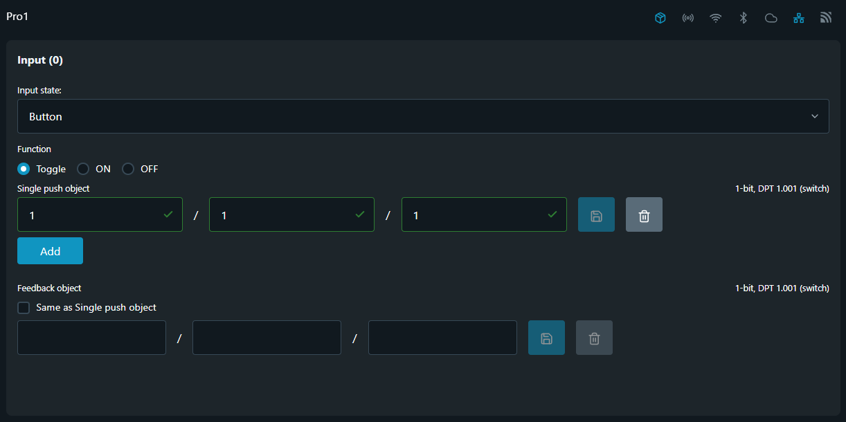
Encoding: 1-bit; DPT 1.001 (switching)
Feedback object field is visible only if TOGGLE Function is selected.
In case when Same as Single push object option is selected and more than one Group address has been provided to the Single push object field the state of object defined by the first Group address is considered.
Input mode - Single button dimming
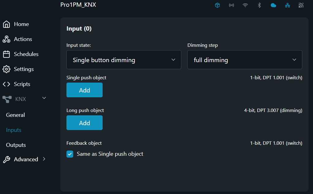
By choosing Single button dimming as Input state it will allow the user to use that input as KNX push button set for single button relative dimming control.
When the input (button) is set to Single button dimming function you can use it to switch the light on or off (via short push) or dim it (via long push). When switching takes place, an ON/OFF telegram is sent via the Single push object. When dimming, dimming up or dimming down is carried out via the 4-bit Long push object. The parameters for the dimming steps can be set from the provided filed with the same name.
The current switching or dimming direction is always dependent on the previous action, i. e. if switched off, pressing the key briefly will switch the light on and vice versa, and if the light has been dimmed up, prolonged activation of the key will dim the light down. On release after prolonged activation, a stop telegram will be sent via the 4-bit dimming object, thus terminating the dimming procedure in the dimming light actuator.
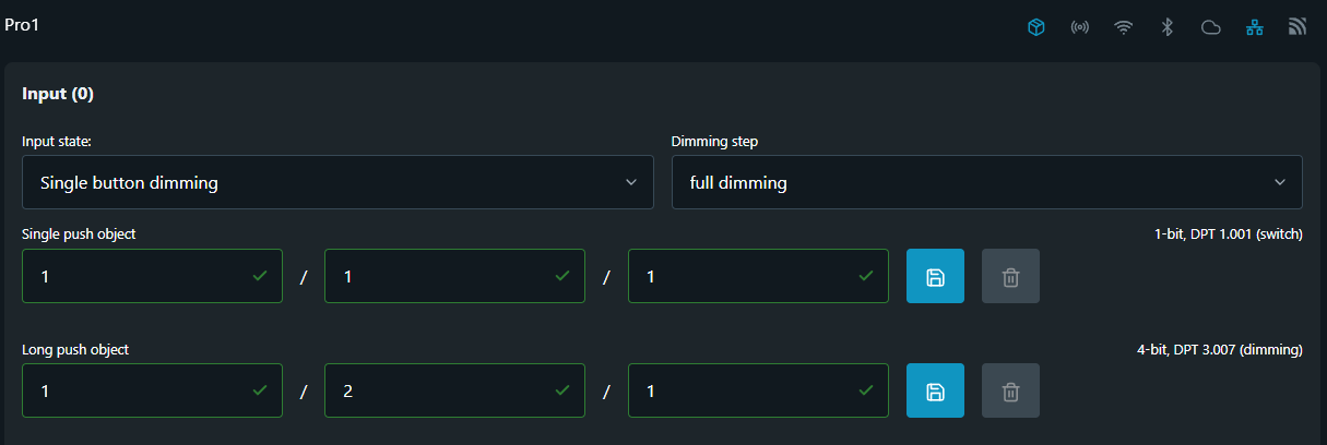
The example below shows how to configure an Input as Single button dimming from KNX menu.
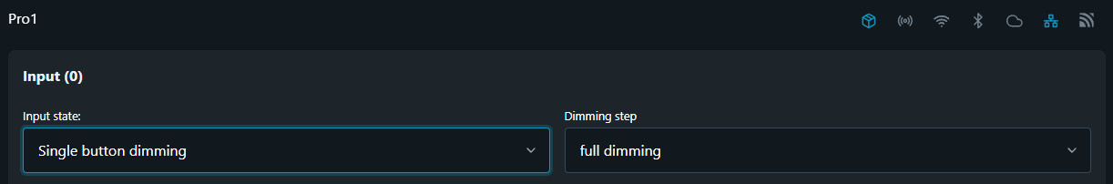
Step 1 - Input state
Navigate to the KNX configuration and select Inputs. From Input state drop-down menu select Single button dimming
Step 2 - Dimming step
The Dimming step field is used to define the dimming interval in steps needed to achieve full dimming range. Desired range is selected via drop-down menu containing 7 different steps to choose from.
Possible Dimming steps are:
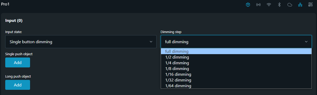
full dimming - selecting this step means that a single command is sufficient to cycle through the whole dimming range. This dimming procedure can be used for most applications.
1/2 to 1/64 dimming - these steps provide partial dimming, capable to dim brighter or darker by the selected step.
For example, to dim from min. to max. brightness, you would need to push the button for a prolonged period (long push) four times in succession if 1/4 dimming step is selected.
Step 3 - Single push object
Add the Group address to the Single push object, then click Save button.
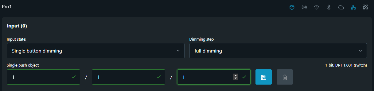
Encoding: 1-bit; DPT 1.001 (switching)
Step 4 - Long push object
Add the Group Address to the Long push object, then click 'Save' button.
The Long push object serves for transmitting to the dimming actuator an encoded data about the dimming direction (UP or DOWN) and also the selected Dimming step.
Encoding: 4-bit; DPT 3.007 (dimming)
Shelly’s single input dimming control has reversed logic comparing to the behavior of KNX dimming push button. This means that with every Long push object our input first transmits a KNX telegram to Increase the dimming output it controls and with the next - to decrease.
Step 5 - Feedback object
Add the Group address to the Feedback object, then click Save button.
Encoding: 1-bit; DPT 1.001 (switching)
Input mode - Dual button dimming
Dual button dimming mode allows the user to configure two independent inputs of a Shelly device to separately DIM UP or DIM DOWN a group of dimming actuators, assigned to the same Group Address.
The two pictures below show an example of Dual button dimming configuration using Input 0 and Input 1.
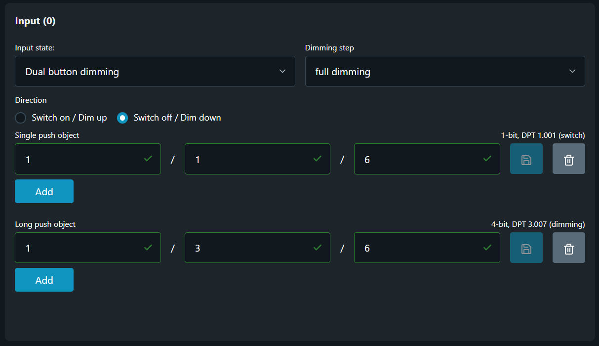
Step 1 - Input state
Navigate to the KNX configuration and select Inputs. From Input state drop-down menu select Dual button dimming.
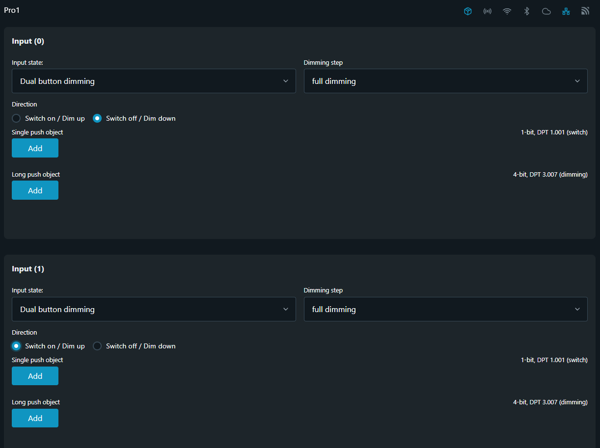
For achieving Dual button dimming mode two separate inputs of a Shelly device are needed.
If the device has more that two inputs you can configure any two inputs.
You can use different Dimming step to DIM DOWN versus the one you're using to DIM UP and vice versa.
Step 2 - Dimming step
The Dimming stepfield is used to define the dimming interval in steps needed to achieve full dimming range. Desired range is selected via in-field drop-down menu containing 7 different steps to choose from.
Possible Dimming steps are:
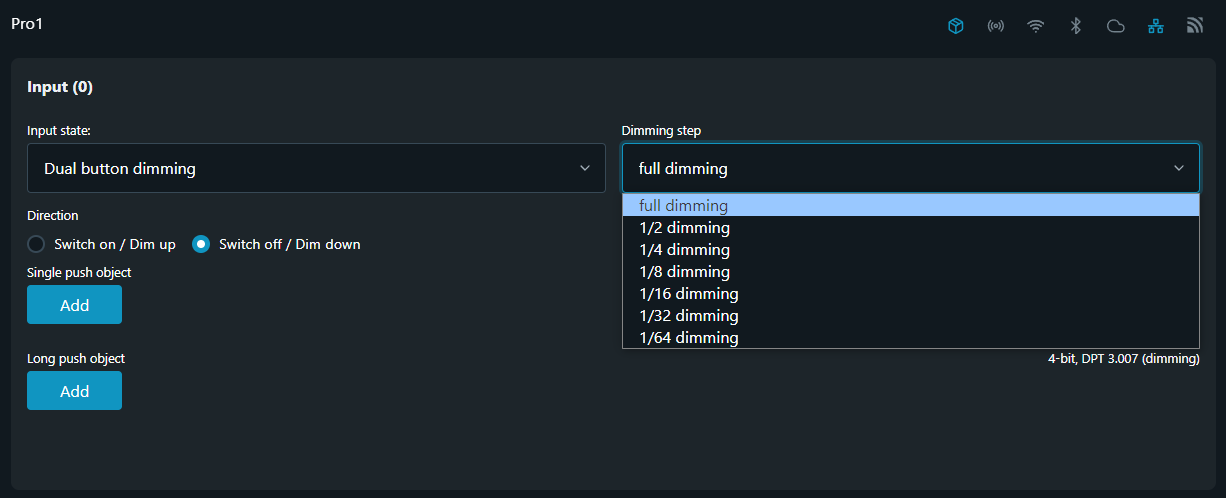
full dimming - selecting this step means that a single command is sufficient to cycle through the whole dimming range. This dimming procedure can be used for most applications.
1/2 to 1/64 dimming - these steps provide partial dimming, capable to dim brighter or darker by the selected step.
For example, to dim from min. to max. brightness, you would need to push the button for a prolonged period (long push) four times in succession if 1/4 dimming step is selected.
Step 3 - Direction
In The Direction section settings you can specify the operations that shall be executed upon short (Single push object) and long activation (Long push object) of the corresponding input. Available options here are:
-
Switch ON / Dim UP
-
Switch OFF / Dim DOWN
Step 4 - Single push object
Add the Group Address to the Single push object, then click 'Save' button.
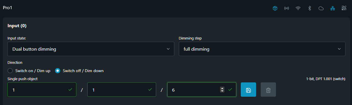
Encoding: 1-bit; DPT 1.001 (switching)
Step 5 - Long push object
Add the Group Address to the Long push object, then click 'Save' button.
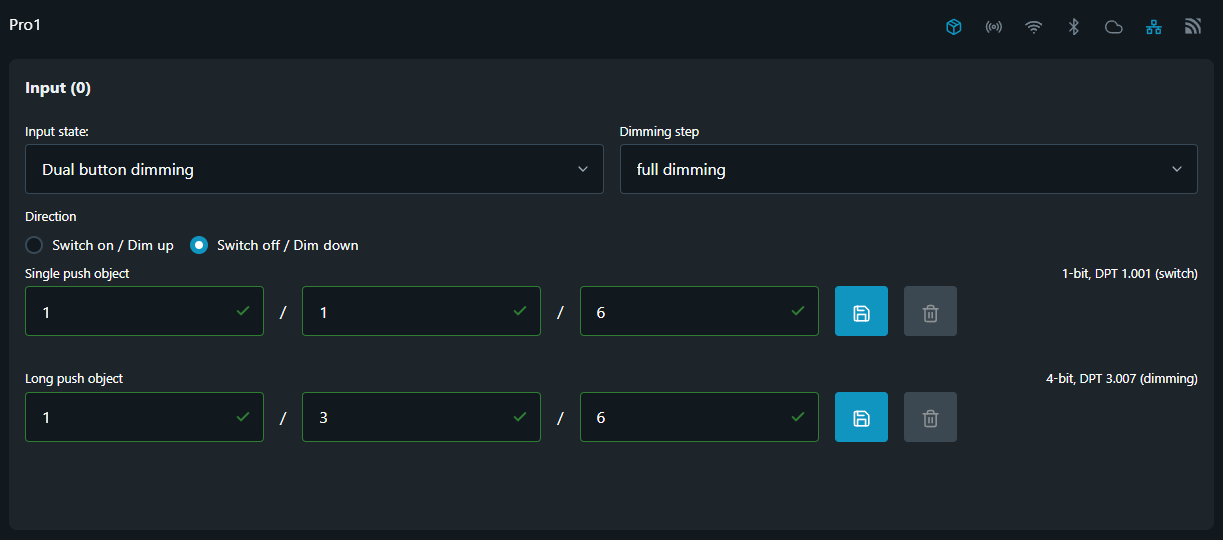
Encoding: 4-bit; DPT 3.007 (dimming)
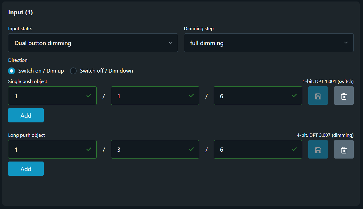
Step 6 - Second input configuration
To configure the second input (second button) repeat all steps from Step 1 to Step 5.
NOTE: Select the inverted option made in Step 3 for the first input!
Alternative configuration
When an input is attached to an output it also may be used to command other devices on the KNX bus. While this is not recommended configuration, if the project calls for such a setup one shall be aware of the limitations arising. Consult the documentation above for setting up the input for role, group addresses and behavior.
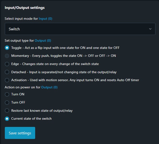
Default input settings are shown in the picture below.