Note: The product line known as "Shelly Qubino Wave" will now be referred to as "Shelly Wave". This name change will not impact the functionality of any devices. The only modification will be the use of the new name in all future documentation.
Device: Wave Shutter
EU Part number/Ordering Code: QNSH-001P10EU
Z-Wave Product type ID: 0x0003
Z-Wave Product ID: 0x0082
Z-Wave Manufacturer: Shelly Europe Ltd.
Z-Wave Manufacturer ID: 0x0460
Terminology
-
Device - In this document, the term “Device” is used to refer to the Shelly Qubino device that is a subject of this guide.
-
Gateway - A Z-Wave® gateway, also referred to as a Z-Wave® controller, Z-Wave® main controller, Z-Wave® primary controller, or Z-Wave® hub, etc., is a device that serves as a central hub for a Z-Wave® smart home network. The term “gateway” is used in this document.
-
S button - The Z-Wave® Service button, located on Z-Wave® devices and is used for various functions such as adding (inclusion), removing (exclusion), and resetting the device to its factory default settings. The term "S button" is used in this document.
-
Adding/Inclusion - The process of adding Z-Wave device to a Z-Wave network - gateway. The words included, added, etc. are used in this regard.
-
Removing/Exclusion - The process of removing Z-Wave device from a Z-Wave network - gateway. The words excluded, removed, etc. are used in this regard.
-
Blind - Refers to any kind of window treatment, such as venetian blinds, roller blinds (screens), roller shutters, vertical window blinds, curtains, integral venetian blinds, pleated blinds, awnings, etc. Additionally, Wave Shutter can also control window motors, projector screens, or any type of bi-directional AC motor.
Short description
The Device enables remote control of motorised blinds, roller shutters, venetian blinds, awnings, etc. It measures power consumption of the connected device.
It is recommended to use only motors for blinds with electronic or mechanical limit switches. Motor limit switches must be set correctly before connecting the Device to the motor.
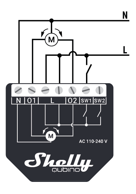
Manual operation for Shutter
Main applications
-
Residential
-
MDU (Multi Dwelling Units - apartments, condominiums, hotels, etc.)
-
Light commercial (small office buildings, small retail/restaurant/gas station, etc.)
-
Government/municipal
-
University/college
Integrations
Shelly Qubino Wave devices are developed on the world's leading technology for smart homes – Z-Wave.
This means Shelly Qubino Wave works with all certified gateways supporting Z-Wave communication protocol.
To make sure the functions of Shelly Qubino Wave products are supported on your gateway, we are regularly executing compatibility tests of our devices with different Z-Wave gateways.
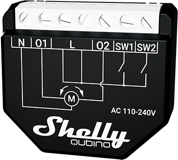
Simplified internal schematics
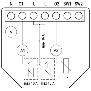
Device electrical interfaces
Inputs
-
2 switch/button input on screw terminal
-
3 power supply inputs on screw terminals: N and L
Outputs
-
2 relay output with power measurement on screw terminal
Connectivity
Z-Wave - Unsecure, S0 Security, S2 Unauthenticated Security, S2 Authenticated Security
Safety features
Over-load detection
Overheat detection
Supported load types
-
Resistive (incandescent bulbs, heating devices)
-
Capacitive (capacitor banks, electronic equipment, motor start capacitors)
-
Inductive with RC Snubber (LED light drivers, transformers, fans, refrigerators, air-conditioners)
User interface
S button and operating modes
-
Normal mode
-
Setting in progress mode
-
Setting mode (with S button)
-
Settings mode is required to start desired procedure for example: adding (inclusion), removing (exclusion), factory reset etc. It has a limited time of operation. After the procedure in Setting mode is concluded, the Device goes automatically into Normal mode.
-
Entering to Setting mode:
-
Quickly press and hold the S button on the Device until the LED turns solid blue
-
An additional quick press on the S button means menu change in infinite loop
-
Menu LED status has a timeout of 10s before entering again into Normal state
-
-
S button’s functions
-
Manually adding the Device to a Z-Wave network
-
Manually removing the Device from a Z-Wave network
-
Factory Reset the Device
Functionality
Automatic calibration is a process during which the Device learns the position of the limit switches.
Note! For the correct position operation, the Device must perform a calibration procedure!
Note! The motor must be equipped with electronic or mechanical limit switches and the limit positions must be set correctly before calibration!
Shutter positioning calibration (Shutter mode)
Parameter No. 71 set to 0.
Calibration with the gateway
3-> default setting (after factory reset) - Parameter 78
1-> start calibration
2-> device is calibrated
3-> device is not calibrated
4-> calibration error
Start calibration:
-
Add the Device to the Z-Wave network according to the instructions for inclusion.
-
Set the Parameter No. 78 (forced Shutter calibration) value to 1.
-
The Device performs the calibration process, completing a full cycle – up, down, up, and down to 50%.
-
Check the Parameter No. 78 to see if the calibration was successfully executed (value 2).
-
Make sure that the yellow LED is not blinking.
Note! In case of values 3 or 4, check if the Device performs the complete cycle of moving (up, down, up, and down to 50%), if the limit switches are set correctly and if the wiring is done according to instructions in the user guide.
Calibration with the push-button (SW1)
-
Move blind to the top (upper) position.
-
Press SW1 4 times in 3 seconds.
-
The Device will start calibration and complete 4 cycles: up, down, up, and down to 50%.
-
Calibration using SW1 is not time-limited!
Calibration with the S button
-
Enter the Setting mode by pressing the S button for less than 0,5 s (short press).
-
Keep pressing the S button until the calibration is selected, indicated by the yellow LED color.
-
Start the calibration by pressing the S button for more than 2 s.
-
Make sure that the yellow LED is not blinking.
Note! If the yellow LED is still blinking, check if the Device performs the complete cycle of moving (up, down, up, and down to 50%), if the limit switches are set correctly and if the wiring is done according to instructions in the user guide.
Slats tilting position calibration (Venetian mode)
Parameter No. 71 set to 1.
When enabling the “venetian blind” mode, position calibration for slats titling must be done. After that, the position and angle of the slats can be set. By default, the rotation time of slats is set to 1,5 s. This value can be changed with the Parameter No. 72.
-
Add (include) and perform the Device calibration process according to the ‘Shutter positioning calibration’ section.
-
Set the Parameter No. 71 to 1 “Venetian blinds”.
-
By default, the full rotation time is set to 1,5 s. If this time is too long (if the blind starts to move up or down after the slats full cycle), decrease this time with the Parameter No. 72. If this time is too short (if the slats do not turn for a full cycle), increase this time with the Parameter No. 72.
-
Repeat the 3rd step until the position of the slats is correct.
Note! If the turning time is set correctly, slats setting should not move blinds up or down.
LED Signalisation
Click to see LED signalisation
General rules
-
To switch between Normal and Setting modes, press the S button once.
-
Solid LED means that the Device is in Setting mode (this does not apply to plugs). When the Device is in Setting mode, it automatically switches to Normal mode after 10s.
-
If the LED is not in Alarm mode, it will turn off after a timeout of 30 min (this does not apply to plugs). Press on the S button or Device power cycle wakes the LED up for 30 min.
Normal mode LED status: Normal mode is defined by a stable Device function that can last infinitely long.
Normal mode
Removed/Excluded / not calibrated
The LED will be blinking blue in Mode 1 for 10 min after every power cycle and 10 min after S button pressed.
Removed/Excluded / calibrated
The LED will be blinking blue and yellow in Mode 1 for 30 min after every power cycle and 10 min after S button pressed.
Added/Included / not calibrated
The LED will be blinking green in Mode 1 for 10 min after every power cycle and 10 min after S button pressed.
Added/Included / calibrated
The LED will be blinking green and yellow in Mode 1 for 30 min after every power cycle and 10 min after S button pressed.
Settings in progress
Factory reset and reboot
During factory reset, the LED will turn solid green for approx. 1sec, then the blue and red LED will be blinking 0,1s On, 0,1s Off for about 2sec.
Adding / Removing
During adding or removing, the LED will be blinking blue in Mode 2.
Shutter calibration
During the calibration, the LED will be blinking yellow in Mode 2.
Settings mode with S button
Adding / Removing menu selected
When the menu is selected the LED will be on blue, for maximum of 10 seconds.
Adding / Removing menu - while pressing S- button - Add/Remove process selected
When the menu is executing the LED will be blinking blue in Mode 3.
Factory reset menu selected
When the menu is selected the LED will be on red, for maximum of 10 seconds.
Factory reset - while pressing S - button - Factory reset process selected
When the menu is executing the LED will be blinking red in Mode 3.
Calibration menu selected
When the menu is selected the LED will be on yellow, for maximum of 10 seconds.
Calibration - while pressing S - button - Calibration process selected
When the menu is executing the LED will be blinking yellow in Mode 3.
Alarm Mode
Over-current detected
The LED will be blinking red in Mode 4 1x - 0,2s On 0,2s Off 2s Off and repeating this sequence
Overheat detected
The LED will be blinking red in Mode 4 - 2x (LED 0,2s On / 0,2s Off) + 2s Off and repeating this sequence
Power supply fault (power supply 230 V AC frequency or 24 V DC voltage fault)
The LED will be blinking red in Mode 4 - 3x (LED 0,2s On / 0,2s Off) + 2s Off and repeating this sequence
LED blinking modes
Specifications
|
Power supply |
110-240 V AC +/- 10% |
|
Power consumption |
< 0.3 W |
|
Power measurement [W] |
Yes |
|
Max switching voltage AC |
240 V |
|
Max switching current AC |
10 A per channel |
|
Overheating protection |
Yes |
|
Overload protection |
Yes |
|
Distance |
up to 40 m indoors (131 ft.)
|
|
Z-Wave® repeater: |
Yes |
|
CPU |
Z-Wave® S800 |
|
Z-Wave® frequency band: |
868,4 MHz |
|
Maximum radio frequency power transmitted in
|
< 25 mW |
|
Size (H x W x D) |
37 x 42 x 16 ± 0.5 mm / 1.46
|
|
Weight |
29g |
|
Mounting |
Wall console |
|
Screw terminals max torque |
0.4 Nm / 3.5 lbin |
|
Conductor cross section |
0.5 to 1.5 mm² / 20 to 16
|
|
Conductor stripped length |
5 to 6 mm / 0.20 to 0.24 in |
|
Shell material |
Plastic |
|
Color |
Black |
|
Ambient temperature |
-20°C to 40°C / -5°F to 105°F |
|
Humidity |
30% to 70% RH |
|
Max. altitude |
2000 m / 6562 ft. |
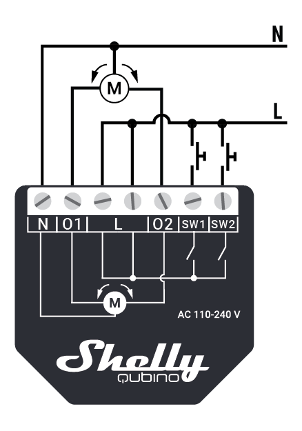
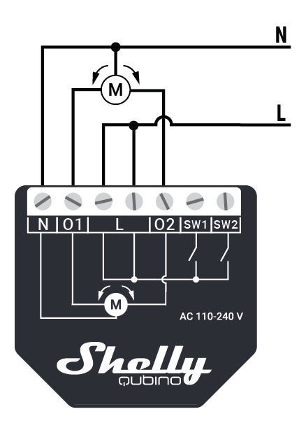
Basic wiring diagram
|

|

|
|
|
|
Legend
|
Terminals |
|
Wires |
|
|---|---|---|---|
|
N |
Neutral terminal |
N |
Neutral wire |
|
L |
Live terminal (110–240 V AC) |
L |
Live (110 - 240 V AC) wire |
|
O1 |
Output terminal for motor UP (open) |
|
|
|
O2 |
Output terminal for motor DOWN (close) |
|
|
|
SW1 |
Input terminal for switch/push-button UP (open) |
|
|
|
SW2 |
Input terminal for switch/push-button UP (close) |
|
|
About Z-Wave
Adding the Device to a Z-Wave® network (inclusion)
Z-Wave Security and Device Specific Key (DSK)
Click to see about the Security and the DSK
The Device supports the latest Security 2 (S2) feature. S2 is handled by the Strong AES 128 Encryption protocol, which means that the S2 makes Z-Wave® the most secure IoT (Internet of Things) security platform out there. To fully utilize the product and its Security 2 feature, a Security 2-enabled Z-Wave® gateway must be used.
Authenticated Control
-
Out-Of-Band DSK for inclusion
-
May be used by most implementations
The Device also supports Security 2 Authenticated, Unauthenticated, and Unsecure inclusion.
Note! When adding the Device to a Z-Wave® network with a gateway supporting Security 2 (S2), the PIN Code of the Z-Wave® Device Specific Key (DSK) is required. The unique DSK code is printed on the DSK label on the side of the Device and a copy is inserted in the packaging, which must not be lost. Do not remove the DSK label from the product. As a backup measure, use the label in the packaging.
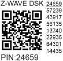
The first five digits of the key are highlighted or underlined to help the user identify the PIN Code part of the DSK text. The DSK is additionally represented with a QR Code as shown on the image.
DSK label and QR code (example)
A joining node requesting to join the S2 Access Control Class or the S2 Authenticated Class will obfuscate its Public Key by setting the bytes 1..2 to zeros (0x00) before transferring its key via RF.
The DSK may be used for out-of-band (OOB) authentication.
-
The including gateway may use a QR code scanning device to read the entire DSK of the joining device and match it with the obfuscated public key received via RF from the joining device.
Z-Wave Parameters
Z-Wave Command Class
Z-Wave Notifications Command Class
Z-Wave Associations
Z-Wave Important disclaimer
Z-Wave® wireless communication may not always be 100% reliable. This Device should not be used in situations in which life and/or valuables are solely dependent on its functioning. If the Device is not recognised by your gateway or appears incorrectly, you may need to change the Device type manually and ensure that your gateway supports Z-Wave Plus™ multi-channel devices.
Troubleshooting
For troubleshooting please visit our support portal: https://support.shelly.cloud/
Compatibility with gateways
Wave Shutterfunctions - reportsGatewayUpDownSW UpSW downWkWhSlatsSW SlatsNotesHome Assistant Fibaro HC 3 / Z-Wave engine 3 Homey Homee Cube Gen 7 *1Homee Cube Gen 5 P PP P *1, *2, *3Smart Things with the Shelly Wave edge driver*4Vera Ezlo Cozify Notes*1 There’s no widget to control the slats*2 The reports from the UI are sent only using the buttons, the slider sends the device to the location but it does not refresh the state.*3 The state is refreshed only after the stop button is pressed. (valid for buttons connected to the SW and the slider in UI)*4 Device is sent to position but the position is not reported
|
Legend |
||||
|
Symbol |
State |
|||
|
|
Working / Possible |
|||
|
❌ |
Not Working / Not Possible |
|||
|
P |
Partially |
|||
|
N/T |
Not Tested |
|||
|
TBD |
To be done |
|||
|
Function |
Meaning / tested |
|---|---|
|
On/Off |
if device respond to the app UI On/Off command |
|
SW On/Off |
if device reports On/Off changes by SW input |
|
Dimming |
if device respond to app UI dimming command |
|
SW Dimming |
if device report dimming state change by SW input |
|
Watts |
if Watts are reported (unsolicited) |
|
kWh |
if kWh are reported (unsolicited) |
|
Up/Down |
if device respond to the app UI Up/Down command |
|
SW Up/Down |
if device reports Up/Down changes by SW input |
|
Slats |
if the slats respond to the app UI command |
|
SW Slats |
if the slats report the changes done by SW |
|
D control |
detached mode if device reports scene commands single press, double press,… |
|
D Binary |
detached mode if the device reports binary On/Off by SW input |
|
Sensor # |
Is the sensor report visualized in the gateway, type of sensor in the notes. |
Components and APIs
The components and APIs depends on the gateway
Compliance
Printed User Guide
Wave Shutter Ръководство за употреба и безопасност.pdf.pdfWave_Shutter_user_guide_multilang_print_V3.pdf