Skip table of contents

Wave Pro 3

Wave_Pro_3_ProductImg_.png

Device identification


Device: Wave Pro 3 (EU)
EU Part number/Ordering Code: QPSW-0A3X16EU
Z-Wave Product type ID: 0x0002
Z-Wave Product ID: 0x0091
Z-Wave Manufacturer: Shelly Europe
Z-Wave Manufacturer ID: 0x0460

Terminology

  • Device - In this document, the term “Device” is used to refer to the Shelly Qubino device that is a subject of this guide.

  • Gateway (GW) - A Z-Wave™ gateway, also referred to as a Z-Wave™ controller, Z-Wave™ main controller, Z-Wave™ primary controller, or Z-Wave™ hub, etc., is a device that serves as a central hub for a Z-Wave™ smart home network. The term “gateway” is used in this document.

  • S button - The Z-Wave™ Service button, located on Z-Wave™ devices and is used for various functions such as adding (inclusion), removing (exclusion), and resetting the device to its factory default settings. The term "S button" is used in this document.

  • Adding/Inclusion - The process of adding Z-Wave device to a Z-Wave network - gateway. The words included, added, etc. are used in this regard.

  • Removing/Exclusion - The process of removing Z-Wave device from a Z-Wave network - gateway. The words excluded, removed, etc. are used in this regard.

Short description

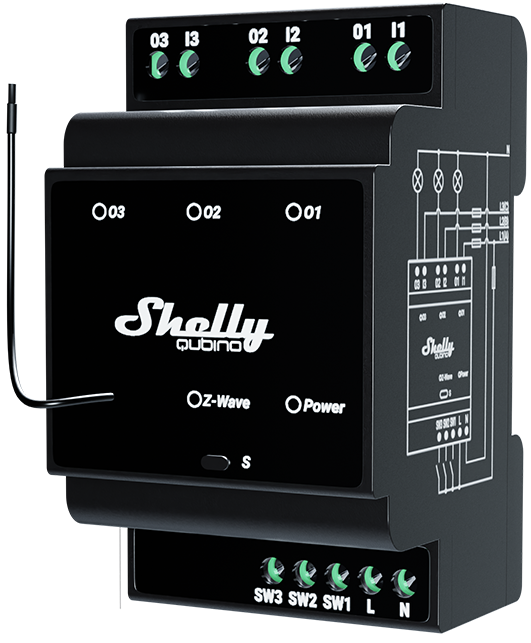
The Device is a DIN rail mountable 3-channel smart switch with potential-free contacts. It controls the on/off function for three independent electrical devices with a load up to 16 A per channel (48 A in total). It is compatible with switches (default) and push-buttons.

Switch/push-button connected to input terminal SW (SW1)

If the SW (SW1) is configured as a switch (default), each toggle of the switch will change the output O (O1) state to the opposite state - on, off, on, etc. If the SW (SW1) is configured as a push-button in the Device settings, each press of the push-button will change the output O (O1) state to the opposite state - on, off, on, etc.

Switch connected to input terminal SW (SW1)

If the SW (SW1) is configured as a switch (default), each toggle of the switch will change the output O (O1) state to the opposite state - on, off, on, etc.

  • Change switch position once: Change the state of the output O (O1) state to the opposite state and send the command to the associated devices in associated groups 2 and 3 (check chapter Z-Wave Association).

Switch-memory connected to input terminal SW (SW1)

If the SW (SW1) is configured as a switch-memory, than:

  • Switching to Close switch-memory contact: Change the state of the output state O (O1) to the On state and send command to the associated devices in associated groups 2 and 3 (check chapter Z-Wave Association)

  • Switching to Open switch-memory contact: Change the state of the output state O (O1) to the Off state and send command to the associated devices in associated groups 2 and 3 (check chapter Z-Wave Association)

Push-button connected to input terminal SW (SW1)

If the SW (SW1) is configured as a push-button in the Device settings, each press of the push-button changes the output state O (O1) to opposite - ON, OFF, ON, etc.

  • 1x click: Change the state of the output state O (O1) to the opposite one and send command to the associated devices in associated groups 2 and 3 (check chapter Z-Wave Association)

  • 2x click: If the delay between first in second click is less then 500ms, this is interpreted as double clik. Send command to the associated devices (dimmers, shutters,….) in associated groups 2 and 3 (check chapter Z-Wave Association)

  • Hold: Send command to the associated devices in associated group 3 (check chapter Z-Wave Association)

  • Release: Send command to the associated devices in associated group 3 (check chapter Z-Wave Association)

Switch/push-button connected to input terminal SW2

If the SW2 is configured as a switch (default), each toggle of the switch will change the output O2 state to the opposite state - on, off, on, etc. If the SW2 is configured as a push-button in the Device settings, each press of the push-button will change the output O2 state to the opposite state - on, off, on, etc.

Switch connected to input terminal SW2

If the SW2 is configured as a switch (default), each toggle of the switch will change the output state O2 to the opposite state - ON, OFF, ON, etc.

  • Change switch position once: Change the state of the output state O2 to the opposite one and send command to the associated devices in associated groups 4 and 5 (check chapter Z-Wave Association).

Switch-memory connected to input terminal SW2

If the SW2 is configured as a switch-memory, than:

  • Switching to Close switch-memory contact: Change the state of the output state O2 to the On state and send command to the associated devices in associated groups 4 and 5 (check chapter Z-Wave Association)

  • Switching to Open switch-memory contact: Change the state of the output state O2 to the Off state and send command to the associated devices in associated groups 4 and 5 (check chapter Z-Wave Association)

Push-button connected to input terminal SW2

If the SW2 is configured as a push-button in the Device settings, each press of the push-button changes the output state O2 to opposite - ON, OFF, ON, etc.

  • 1x click: Change the state of the output state O2 to the opposite one and send command to the associated devices in associated groups 4 and 5 (check chapter Z-Wave Association)

  • 2x click: If the delay between first in second click is less then 500ms, this is interpreted as double clik. Send command to the associated devices (dimmers, shutters,….) in associated groups 4 and 5 (check chapter Z-Wave Association)

  • Hold: Send command to the associated devices in associated group 4 (check chapter Z-Wave Association)

  • Release: Send command to the associated devices in associated group 5 (check chapter Z-Wave Association)

Switch/push-button connected to input terminal SW3

If the SW3 is configured as a switch (default), each toggle of the switch will change the output O3 state to the opposite state - on, off, on, etc. If the SW3 is configured as a push-button in the Device settings, each press of the push-button will change the output O3 state to the opposite state - on, off, on, etc.

Switch connected to input terminal SW3

If the SW3 is configured as a switch (default), each toggle of the switch will change the output state O3 to the opposite state - ON, OFF, ON, etc.

  • Change switch position once: Change the state of the output state O3 to the opposite one and send command to the associated devices in associated groups 6 and 7 (check chapter Z-Wave Association)

Switch-memory connected to input terminal SW3

If the SW3 is configured as a switch-memory, than:

  • Switching to Close switch-memory contact: Change the state of the output state O3 to the On state and send command to the associated devices in associated groups 6 and 7 (check chapter Z-Wave Association)

  • Switching to Open switch-memory contact: Change the state of the output state O3 to the Off state and send command to the associated devices in associated groups 6 and 7 (check chapter Z-Wave Association)

Push-button connected to input terminal SW3

If the SW3 is configured as a push-button in the Device settings, each press of the push-button changes the output state O3 to opposite - ON, OFF, ON, etc.

  • 1x click: Change the state of the output state O3 to the opposite one and send command to the associated devices in associated groups 6 and 7 (check chapter Z-Wave Association)

  • 2x click: If the delay between first in second click is less then 500ms, this is interpreted as double click. Send command to the associated devices (dimmers, shutters,….) in associated groups 6 and 7 (check chapter Z-Wave Association)

  • Hold: Send command to the associated devices in associated group 6 (check chapter Z-Wave Association)

  • Release: Send command to the associated devices in associated group 7 (check chapter Z-Wave Association)

Main applications

  • Residential

  • MDU (Multi Dwelling Units - apartments, condominiums, hotels, etc.)…

  • Light commercial (small office buildings, small retail/restaurant/gas station, etc.)…

  • Industrial (factories, power plants, water processing, refineries, etc.)…

  • Government/municipal

  • University/college

  • Farming

Integrations

Shelly Qubino Wave devices are developed on the world's leading technology for smart homes – Z-Wave.

This means Shelly Qubino Wave works with all certified gateways supporting Z-Wave communication protocol.

To make sure the functions of Shelly Qubino Wave products are supported on your gateway, we are regularly executing compatibility tests of our devices with different Z-Wave gateways.

Simplified internal schematics

Shelly Pro 3 simplified internal schematics

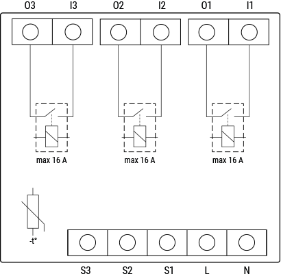
Device electrical interfaces

Inputs

  • 3 switch/push-button inputs on screw terminal


  • 3 potential-free contact relay inputs on screw terminal


  • 2 power supply inputs on screw terminals: N , L

Outputs

  • 3 potential-free contacts relay outputs on screw terminal

Connectivity

Z-Wave - Unsecure, S0 Security, S2 Unauthenticated Security, S2 Authenticated Security

Safety features

Overheat protection

Supported load types

  • Resistive (incandescent bulbs, heating devices)


  • Capacitive (capacitor banks, electronic equipment, motor start capacitors)


  • Inductive with RC Snubber (LED light drivers, transformers, fans, refrigerators, air-conditioners)

User interface

S button and operating modes

  • Settings mode:

Is required to start the desired procedure, for example: adding (inclusion), removing (exclusion), factory reset, etc. It has a limited operating time. After completing the procedure in Setting mode, the Device automatically switches to Normal mode.

  • Entering Setting mode:

    • Press and hold the S button on the Device until the LED turns solid blue.

    • An additional quick press on the S button changes the menu in an infinite loop.

    • The Menu LED status has a timeout of 10s before entering again into Normal mode.


S button’s functions

  • Manually adding the Device to a Z-Wave network

  • Manually removing the Device from a Z-Wave network

  • Factory Reset the Device

LED Signalisation

Click to see LED signalisation

Zwave LED


LED type: RGB dimmable


General rules

  • Switching between Normal and Settings mode is done by press and hold the S button

  • Solid LED means that you are in the Settings mode (this is not valid for Plugs). Ones in settings mode, switch to normal mode goes automatically after 10s

  • If the LED is not in Alarm mode, it will turn off after a timeout of 30 min. Pressing the S button or power cycling the Device will wake the LED for 30 min.

Normal mode LED status: Normal mode is defined by stable device function that can remain for an infinite time.

Normal mode
Removed/Excluded

The LED will be blinking blue in Mode 1 for 30 min after every power cycle and 10 min after S button pressed.

Added/Included

The LED will be blinking green in Mode 1 for 30 min after every power cycle and 10 min after S button pressed.


Settings in progress

Factory reset and reboot

During factory reset, the LED will turn solid green for approx. 1sec, then the blue and red LED will be blinking 0,1s On / 0,1s Off for about 2sec. 

Adding / Removing

During adding or removing, the LED will be blinking blue in Mode 2.

OTA firmware updating

During the OTA update, the LED will be blinking blue and red in Mode 2.

Checking power supply 230 V AC frequency or 24 V DC voltage

During checking the power supply, the LED will be blinking blue and red in Mode 5.

Settings mode with S button

Adding / Removing menu selected

When the menu is selected the LED will be on blue, for maximum of 10 seconds.

Adding / Removing menu - while pressing S- button - Add/Remove process selected

When the menu is executing the LED will be blinking blue in Mode 3.

Factory reset menu selected

When the menu is selected the LED will be on red, for maximum of 10 seconds.

Factory reset  - while pressing S - button - Factory reset process selected

When the menu is executing the LED will be blinking red in Mode 3.

Alarm Mode

Overheat detected 

The LED will be blinking red in Mode 4

Mode 4 / 2x (LED 0,2s On / 0,2s Off) + 2s Off repeating sequence

Power LED

LED type: Red

The LED will be red solid if power supply is connected.

Output (O, O1, O2,…) LED

LED type: Red

The LED will be red solid if the Output relay is closed.

Removed/Excluded

The LED will be blinking blue in Mode 1 for 10 min after every power cycle and 10 min after S button pressed.

Added/Included

The LED will be blinking green in Mode 1 for 10 min after every power cycle and 10 min after S button pressed.


Settings in progress

Factory reset and reboot

During factory reset, the LED will turn solid green for approx. 1sec, then the blue and red LED will be blinking 0,1s On, 0,1s Off for about 2sec. 

Adding / Removing

During adding or removing, the LED will be blinking blue in Mode 2.

Firmware updating OTA

During the OTA update, the LED will be blinking blue and red in Mode 2.

Checking power supply 230 V AC frequency or 24 V DC voltage

During checking the power supply, the LED will be blinking blue and red in Mode 5.

Settings mode with S button

Adding / Removing menu selected

When the menu is selected the LED will be on blue, for maximum of 10 seconds.

Adding / Removing menu - while pressing S- button - Add/Remove process selected

When the menu is executing the LED will be blinking blue in Mode 3.

Factory reset menu selected

When the menu is selected the LED will be on red, for maximum of 10 seconds.

Factory reset  - while pressing S - button - Factory reset process selected

When the menu is executing the LED will be blinking red in Mode 3.

Alarm Mode

Overheat detected 

The LED will be blinking red in Mode 4 2x - 0,2s On 0,2s Off  0,2s On 0,2s Off 2s Off and repeating this sequence

LED blinking modes

Click to see the LED blinking modes

LED blinking modes

Mode 1

0,5s On/2s Off

Mode 2

0,5s On/0,5s Off

Mode 3

0,1s On/0,1s Off

Mode 4

(1x to 6x - 0,2s On/0,2s Off) + 2s Off

Mode 5

0,2s On blue/0,2s On red

Specifications

Power supply

110 - 240 V AC, 50/60 Hz

Power consumption

< 0.3W

Max. switching voltage AC

240 V

Max. switching current AC

16 A per channel, 48 A total

Max. switching voltage DC

30 V

Max. switching current DC

16 A per channel, 48 A total

Overheating protection

Yes

Distance

Up to 40 m indoors (131 ft.) (depends on local condition)

Z-Wave® repeater:

Yes

CPU

Z-Wave® S800

Z-Wave® frequency bands

868.4 MHz

Maximum radio frequency power transmitted in frequency band(s)

< 25 mW

Size (H x W x D)

96x53x59 ± 0.5 mm / 3.78x2.01x2.32 ± 0.02 in

Weight

150 g / 5.29 oz

Mounting

DIN rail

Screw terminals max. torque

0.4 Nm / 3.54 lbin

Conductor cross section

0.5 to 2.5 mm² / 20 to 14 AWG (green connector)

Conductor stripped length

6 to 7 mm / 0.24 to 0.28 in (green connector)

Shell material

Plastic

Color

Black

Ambient temperature

-20°C to 40°C / -5°F to 105°F

Humidity

30% to 70% RH

Max. altitude

2000 m / 6562 ft.

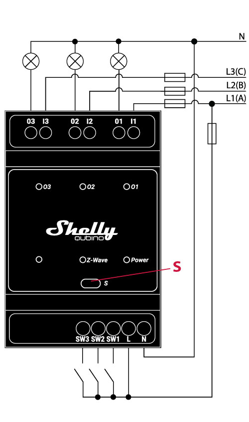
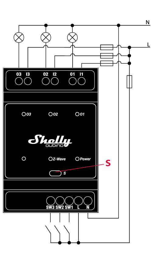
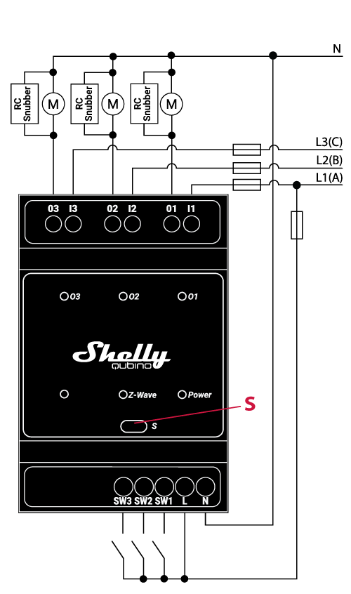
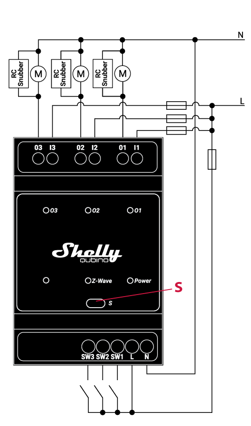
Basic wiring diagram

Wave_Pro_3_electric_diagram_V1_w.png

Fig. 1

Wave_Pro_3_electric_diagram_V2_w.png

Fig. 2

Legend

Device terminals:

  • N: Neutral terminal

  • L: Live terminal (110-240 V AC)

  • SW (SW1): Switch/push-button input terminal (controlling O (O1))

  • SW2: Switch/push-button input terminal (controlling O2)

  • SW3: Switch/push-button input terminal (controlling O3)

  • I1: Load circuit 1 input terminal

  • I2: Load circuit 2 input terminal

  • I3: Load circuit 3 input terminal

  • O (O1): Load circuit (1) output terminal

  • O2: Load circuit 2 output terminal

  • O3: Load circuit 3 output terminal
    Wires:

  • N: Neutral wire

  • L1(A): Load circuit 1 live wire (110-240 V AC)

  • L2(B): Load circuit 2 live wire (110-240 V AC)

  • L3(C): Load circuit 3 live wire (110-240 V AC)
    Button:

  • S: S button

About Z-Wave®

Adding and removing the Device to a Z-Wave® network 

Click to see how to add, remove and reset the Device

Adding the Device to a Z-Wave® network (inclusion)


Note! All Device outputs (O, O1, O2, etc. - depending on the Device type) will turn the load 1s on/1s off /1s on/1s off if the Device is successfully added to/removed from a Z-Wave® network.


Note! In case of Security 2 (S2) adding (inclusion), a dialog will appear asking you to enter the corresponding PIN Code (5 underlined digits) that are written on the Z-Wave® DSK label on the side of the Device and on the Z-Wave® DSK label inserted in the packaging.
IMPORTANT: The PIN Code must not be lost.


SmartStart adding (inclusion)

SmartStart enabled products can be added into a Z-Wave® network by scanning the Z-Wave® QR Code present on the Device with a gateway providing SmartStart inclusion. No further action is required, and the SmartStart device will be added automatically within 10 minutes of being switched on in the network vicinity.

  1. With the gateway application scan the QR code on the Device label and add the Security 2 (S2) Device Specific Key (DSK) to the provisioning list in the gateway.

  2. Connect the Device to a power supply.

  3. Check if the blue LED is blinking in Mode 1. If so, the Device is not added to a Z-Wave® network.

  4. Adding will be initiated automatically within a few seconds after connecting the Device to a power supply, and the Device will be added to a Z-Wave® network automatically.

  5. The blue LED will be blinking in Mode 2 during the adding process.

  6. The green LED will be blinking in Mode 1 if the Device is successfully added to a Z-Wave® network.

Adding (inclusion) with the S button
  1. Connect the Device to a power supply.

  2. Check if the blue LED is blinking in Mode 1. If so, the Device is not added to a Z-Wave® network.

  3. Enable add/remove mode on the gateway.

  4. To enter the Setting mode, press and hold the S button on the Device until the LED turns solid blue.

  5. Release and then press and hold (> 2s) the S button on the Device until the blue LED starts blinking in Mode 3. Releasing the S button will start the Learn mode.

  6. The blue LED will be blinking in Mode 2 during the adding process.

  7. The green LED will be blinking in Mode 1 if the Device is successfully added to a Z-Wave® network.

Note! In Setting mode, the Device has a timeout of 10s before entering again into Normal mode.


Adding (inclusion) with a switch/push-button
  1. Connect the Device to a power supply.

  2. Check if the blue LED is blinking in Mode 1. If so, the Device is not added to a Z-Wave® network.

  3. Enable add/remove mode on the gateway.

  4. Toggle the switch/push-button connected to any of the SW terminals (SW, SW1, SW2, etc.) 3 times within 3 seconds (this procedure puts the Device in Learn mode*). The Device must receive on/off signal 3 times, which means pressing the momentary switch 3 times, or toggling the switch on and off 3 times.

  5. The blue LED will be blinking in Mode 2 during the adding process.

  6. The green LED will be blinking in Mode 1 if the Device is successfully added to a Z-Wave® network.

*Learn mode - a state that allows the Device to receive network information from the gateway.

Removing the Device from a Z-Wave® network (exclusion)

Note! The Device will be removed from your Z-Wave® network, but any custom configuration parameters will not be erased.


Note! All Device outputs (O, O1, O2, etc. - depending on the Device type) will turn the load 1s on/1s off /1s on/1s off if the Device is successfully added to/removed from a Z-Wave® network.


Removing (exclusion) with the S button
  1. Connect the Device to a power supply.

  2. Check if the green LED is blinking in Mode 1. If so, the Device is added to a Z-Wave® network.

  3. Enable add/remove mode on the gateway.

  4. To enter the Setting mode, press and hold the S button on the Device until the LED turns solid blue.

  5. Release and then press and hold (> 2s) the S button on the Device until the blue LED starts blinking in Mode 3. Releasing the S button will start the Learn mode.

  6. The blue LED will be blinking in Mode 2 during the removing process.

  7. The blue LED will be blinking in Mode 1 if the Device is successfully removed from a Z-Wave® network.

Note! In Setting mode, the Device has a timeout of 10s before entering again into Normal mode.


Removing (exclusion) with a switch/push-button
  1. Connect the Device to a power supply.

  2. Check if the green LED is blinking in Mode 1. If so, the Device is added to a Z-Wave® network.

  3. Enable add/remove mode on the gateway.

  4. Toggle the switch/push-button connected to any of the SW terminals (SW, SW1, SW2,…) 3 times within 3 seconds (this procedure puts the Device in Learn mode). The Device must receive on/off signal 3 times, which means pressing the momentary switch 3 times, or toggling the switch on and off 3 times.

  5. The blue LED will be blinking in Mode 2 during the removing process.

  6. The blue LED will be blinking in Mode 1 if the Device is successfully removed from a Z-Wave® network.

Factory reset

Factory reset general

After Factory reset, all custom parameters and stored values (kWh, associations, routings, etc.) will return to their default state. HOME ID and NODE ID assigned to the Device will be deleted. Use this reset procedure only when the gateway is missing or otherwise inoperable.


Factory reset with the S button

Note! Factory reset with the S button is possible anytime.

  1. To enter the Setting mode, press and hold the S button on the Device until the LED turns solid blue.

  2. Press the S button multiple times until the LED turns solid red.

  3. Press and hold (> 2s) S button on the Device until the red LED starts blinking in Mode 3. Releasing the S button will start the factory reset.

  4. During factory reset, the LED will turn solid green for about 1s, then the blue and red LED will start blinking in Mode 3 for approx. 2s.

  5. The blue LED will be blinking in Mode 1 if the Factory reset is successful.


Factory reset with a switch/push-button

Note! Factory reset with a switch/push-button is only possible within the first minute after the Device is connected to a power supply.

  1. Connect the Device to a power supply.

  2. Toggle the switch/push-button connected to any of the SW terminals (SW, SW1, SW2,…) 5 times within 3 seconds. The Device must receive on/off signal 5 times, which means pressing the push-button 5 times, or toggling the switch on and off 5 times.

  3. During factory reset, the LED will turn solid green for about 1s, then the blue and red LED will start blinking in Mode 3 for approx. 2s.

  4. The blue LED will be blinking in Mode 1 if the Factory reset is successful.


Remote factory reset with parameter with a gateway

Factory reset can be done remotely with the settings in Parameter No. 120.

Z-Wave® Security and Device Specific Key (DSK)

Click to see about the Security and the DSK

The Device supports the latest Security 2 (S2) feature. S2 is handled by the Strong AES 128 Encryption protocol, which means that the S2 makes Z-Wave® the most secure IoT (Internet of Things) security platform out there. To fully utilize the product and its Security 2 feature, a Security 2-enabled Z-Wave® gateway must be used.

Authenticated Control

  • Out-Of-Band DSK for inclusion

  • May be used by most implementations

The Device also supports Security 2 Authenticated, Unauthenticated, and Unsecure inclusion. 

Note! When adding the Device to a Z-Wave® network with a gateway supporting Security 2 (S2), the PIN Code of the Z-Wave® Device Specific Key (DSK) is required. The unique DSK code is printed on the DSK label on the side of the Device and a copy is inserted in the packaging, which must not be lost. Do not remove the DSK label from the product. As a backup measure, use the label in the packaging. 

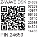
The first five digits of the key are highlighted or underlined to help the user identify the PIN Code part of the DSK text. The DSK is additionally represented with a QR Code as shown on the image.

DSK label and QR code (example)

A joining node requesting to join the S2 Access Control Class or the S2 Authenticated Class will obfuscate its Public Key by setting the bytes 1..2 to zeros (0x00) before transferring its key via RF.

The DSK may be used for out-of-band (OOB) authentication.

  • The including gateway may use a QR code scanning device to read the entire DSK of the joining device and match it with the obfuscated public key received via RF from the joining device.

Z-Wave® Parameters

Click here to see the Z-Wave Parameters

Parameter No. 1 - SW (SW1) Switch type

This parameter defines how the Device should treat the switch (which type) connected to the SW (SW1) terminal.

Value size: 1 Byte

Default value: 2

Values & descriptions:

  • 0 - momentary switch (push button),

  • 1 - toggle switch (contact closed - ON / contact opened - OFF),

  • 2 - toggle switch (Device changes status when switch changes status)

Parameter No. 2 - SW2 Switch type

This parameter defines how the Device should treat the switch (which type) connected to the SW2 terminal.

Value size: 1 Byte

Default value: 2

Values & descriptions:

  • 0 - momentary switch (push button),

  • 1 - toggle switch (contact closed - ON / contact opened - OFF),

  • 2 - toggle switch (device changes status when switch changes status)

Parameter No. 3 - SW3 Switch type

This parameter defines how the Device should treat the switch (which type) connected to the SW3 terminal.

Value size: 1 Byte

Default value: 2

Values & descriptions:

  • 0 - momentary switch (push button),

  • 1 - toggle switch (contact closed - ON / contact opened - OFF),

  • 2 - toggle switch (device changes status when switch changes status)

Parameter No. 17 - Restore the O (O1) state after a power failure

This parameter determines if the on/off status is saved and restored for the load connected to O (O1) after a power failure.

Values size: 1 Byte

Default value: 0

Values & descriptions:

  • 0 - Device saves last on/off status and restores it after a power failure

  • 1 - Device does not save on/off status and does not restore it after a power failure, it remains off

Parameter No. 18 - Restore the O2 state after a power failure

This parameter determines if the on/off status is saved and restored for the load connected to O2 after a power failure.

Values size: 1 Byte

Default value: 0

Values & descriptions:

  • 0 - Device saves last on/off status and restores it after a power failure

  • 1 - Device does not save on/off status and does not restore it after a power failure, it remains off

Parameter No. 19 - O (O1) Auto OFF with timer

If the load O (O1) is ON, you can schedule it to turn OFF automatically after the period of time defined in this parameter. The timer resets to zero each time the Device receives an ON command, either remotely (from the gateway or associated device) or locally from the switch.

Values size: 2 Byte

Default value: 0

Values & their descriptions:

  • 0 - Auto OFF Disabled

  • 1 - 32535 = 1 - 32535 seconds or milliseconds – see Parameter no. 25. Set timer units to s or ms for O (O1) resolution 100ms

Parameter No. 20 - O (O1) Auto ON with timer

If the load O (O1) is OFF, you can schedule it to turn ON automatically after the period of time defined in this parameter. The timer resets to zero each time the Device receives an OFF command, either remotely (from the gateway or associated device) or locally from the switch.

Values size: 2 Byte

Default value: 0

Values & their descriptions:

  • 0 - Auto ON Disabled

  • 1 - 32535 = 1 - 32535 seconds or milliseconds – see Parameter no. 25. Set timer units to s or ms for O (O1) resolution 100ms

Parameter No. 21 - O2 Auto OFF with timer

If the load O2 is ON, you can schedule it to turn OFF automatically after the period of time defined in this parameter. The timer resets to zero each time the device receives an ON command, either remotely (from the gateway or associated device) or locally from the switch.

Values size: 2 Byte

Default value: 0

Values & their descriptions:

  • 0 - Auto OFF Disabled

  • 1 - 32535 = 1 - 32535 seconds or milliseconds – see Parameter no. 26. Set timer units to s or ms for O2 resolution 100ms

Parameter No. 22 - O2 Auto ON with timer

If the load O2 is OFF, you can schedule it to turn ON automatically after the period of time defined in this parameter. The timer resets to zero each time the device receives an OFF command, either remotely (from the gateway or associated device) or locally from the switch.

Values size: 2 Byte

Default value: 0

Values & their descriptions:

  • 0 - Auto ON Disabled

  • 1 - 32535 = 1 - 32535 seconds or milliseconds – see Parameter no. 26. Set timer units to s or ms for O2 resolution 100ms

Parameter No. 23 - O (O1) contact type - NO/NC

The set value determines the relay contact type for output O (O1). The relay contact type can be normally open (NO) or normally closed (NC).

Values size: 1 Byte

Default value: 0

Values & descriptions:

  • 0 - NO

  • 1 - NC

Relay logic:

Par-NO/NC

Command (switch, Z-Wave…)

Device output state

NO (0)

OFF

OFF (0 V)

NO (0)

ON

ON (230 V)

NC (1)

OFF

ON (230 V)

NC (1)

ON

OFF (0 V)

Parameter No. 24 - O2 contact type - NO/NC

The set value determines the type of Relay contact type for O2 output. The Relay contact type can be normally open (NO) or normally closed (NC).

Values size: 1 Byte

Default value: 0

Values & descriptions:

  • 0 - NO

  • 1 - NC

Relay logic:

par-NO/NC

command (switch, zwave,..)

Device output state

NO (0)

OFF

OFF (0V)

NO (0)

ON

ON (230V)

NC (1)

OFF

ON (230V)

NC (1)

ON

OFF (0V)

Parameter No. 25 - Set timer units to s or ms for O (O1)

Set the timer units to seconds or milliseconds. Choose if you want to set the timer in seconds or milliseconds in Parameters No. 19, 20.

Values size: 1 Byte

Default value: 0

Values & descriptions:

  • 0 – timer set in seconds

  • 1 – timer set in milliseconds

Parameter No. 26 - Set timer units to s or ms for O2

Set the timer units to seconds or milliseconds. Choose if you want to set the timer in seconds or milliseconds in Parameters No. 21, 22.

Values size: 1 Byte

Default value: 0

Values & descriptions:

  • 0 – timer set in seconds

  • 1 – timer set in milliseconds

Parameter No. 27 - Restore the O3 state after a power failure

This parameter determines if the on/off status is saved and restored for the load connected to O3 after a power failure.

Values size: 1 Byte

Default value: 0

Values & descriptions:

  • 0 - Device saves last on/off status and restores it after a power failure

  • 1 - Device does not save on/off status and does not restore it after a power failure, it remains off

Parameter No. 29 - O3 Auto OFF with timer

If the load O3 is ON, you can schedule it to turn OFF automatically after the period of time defined in this parameter. The timer resets to zero each time the device receives an ON command, either remotely (from the gateway or associated device) or locally from the switch.

Values size: 2 Byte

Default value: 0

Values & their descriptions:

  • 0 - Auto OFF Disabled

  • 1 - 32535 = 1 - 32535 seconds (or milliseconds – see Parameter no. 26. Auto OFF timer enabled for a given amount of seconds (or milliseconds) resolution 100ms

Parameter No. 30 - O3 Auto ON with timer

If the load O3 is OFF, you can schedule it to turn ON automatically after the period of time defined in this parameter. The timer resets to zero each time the device receives an OFF command, either remotely (from the gateway or associated device) or locally from the switch.

Values size: 2 Byte

Default value: 0

Values & their descriptions:

  • 0 - Auto ON Disabled

  • 1 - 32535 = 1 - 32535 seconds (or milliseconds – see Parameter no. 26. Auto ON timer enabled for a given amount of seconds (or milliseconds) resolution 100ms

Parameter No. 91 - Water Alarm

This parameter determines how the device should respond to the reports of alarm frames. The parameters consist of 4 bytes, the three most significant bytes are set according to the official Z-Wave protocol specification.

The notification types it reacts to are as followed:

Notification Type:

  • NOTIFICATION_TYPE_WATER_ALARM 0x05

Notification Events:

  • All except ALARM_NO_EVENT 0x00

Values size: 4 Byte
Default value: 0
Values & descriptions:

  • 0 no action

  • 1 open relay

  • 2 close relay

Parameter No. 92 - Smoke Alarm

This parameter determines how the device should respond to the reports of alarm frames. The parameters consist of 4 bytes, the three most significant bytes are set according to the official Z-Wave protocol specification.

The notification types it reacts to are as followed:

Notification Type:

  • NOTIFICATION_TYPE_SMOKE_ALARM 0x01

Notification Events:

  • NOTIFICATION_EVENT_SMOKE_ALARM_SMOKE_DETECTED 0x01

  • NOTIFICATION_EVENT_SMOKE_ALARM_SMOKE_DETECTED_UNKNOWN_LOCATION 0x02

Values size: 4 Byte
Default value: 0
Values & descriptions:

  • 0 no action

  • 1 open relay

  • 2 close relay

Parameter No. 93 - CO Alarm

This parameter determines how the device should respond to the reports of alarm frames. The parameters consist of 4 bytes, the three most significant bytes are set according to the official Z-Wave protocol specification.

The notification types it reacts to are as followed:

Notification Type:

  • NOTIFICATION_TYPE_CO_ALARM 0x02

Notification Events:

  • All except ALARM_NO_EVENT 0x00

Values size: 4 Byte
Default value: 0
Values & descriptions:

  • 0 no action

  • 1 open relay

  • 2 close relay

Parameter No. 94 - Heat Alarm

This parameter determines how the device should respond to the reports of alarm frames. The parameters consist of 4 bytes, the three most significant bytes are set according to the official Z-Wave protocol specification.

The notification types it reacts to are as followed:

Notification Type:

  • NOTIFICATION_TYPE_HEAT_ALARM 0x04

Notification Events:

  • NOTIFICATION_EVENT_HEAT_ALARM_RAPID_TEMPERATURE_RISE_LOCATION_PROVIDED 0x03

  • NOTIFICATION_EVENT_HEAT_ALARM_RAPID_TEMPERATURE_RISE 0x04

  • NOTIFICATION_EVENT_HEAT_ALARM_RAPID_TEMPERATURE_FALL_LOCATION_PROVIDED 0x0C

  • NOTIFICATION_EVENT_HEAT_ALARM_RAPID_TEMPERATURE_FALL 0x0D

Values size: 4 Byte
Default value: 0
Values & descriptions:

  • 0 no action

  • 1 open relay

  • 2 close relay

Parameter No. 106 - O3 contact type - NO/NC

The set value determines the type of Relay contact type for O3 output. The Relay contact type can be normally open (NO) or normally closed (NC).

Values size: 1 Byte

Default value: 0

Values & descriptions:

  • 0 - NO

  • 1 - NC

Relay logic:

par-NO/NC

command (switch, zwave,..)

Device output state

NO (0)

OFF

OFF (0V)

NO (0)

ON

ON (230V)

NC (1)

OFF

ON (230V)

NC (1)

ON

OFF (0V)

Parameter No. 108 - Set timer units to s or ms for O3

Set the timer units to seconds or milliseconds. Choose if you want to set the timer in seconds or milliseconds in Parameters No. 29, 30.

Values size: 1 Byte

Default value: 0

Values & descriptions:

  • 0 – timer set in seconds

  • 1 – timer set in milliseconds

Parameter No. 120 - Factory Reset

Reset to factory default settings and removed from the Z-Wave network.

The parameter is Advanced and may be hidden under the Advanced tag.

Values size: 4 Byte

Default value: 0

Values & descriptions:

  • 0 - No action

  • 1 - Factory reset

After reset is performed, the parameter value is automatically set to 0.1


Parameter No. 201 - Serial Number 1

This parameter contains a part of device’s serial number.

The parameter is Read-Only and cannot be changed.
The parameter is Advanced and may be hidden under the Advanced tag.

Values size: 4 Byte

Default value: Device specific

Values & descriptions:

·         0x00000000 - 0x7FFFFFFF


Parameter No. 202 - Serial Number 2

This parameter contains a part of device’s serial number.

The parameter is Read-Only and cannot be changed.
The parameter is Advanced and may be hidden under the Advanced tag.

Values size: 4 Byte

Default value: Device specific

Values & descriptions:

·         0x00000000 - 0x7FFFFFFF


Parameter No. 203 - Serial Number 3

This parameter contains a part of device’s serial number.

The parameter is Read-Only and cannot be changed.
The parameter is Advanced and may be hidden under the Advanced tag.

Values size: 4 Byte

Default value: Device specific

Values & descriptions:

·         0x00000000 - 0x7FFFFFFF

Z-Wave® Command Classes

Click to see the Z-Wave Command Classes
  1. ASSOCIATION_V2 [S0, S2]*

  2. ASSOCIATION_GRP_INFO_V3 [S0, S2]*

  3. BASIC_V2 [S0, S2]*

  4. SWITCH_BINARY_V2 [S0, S2]*

  5. CONFIGURATION_V4 [S0, S2]*

  6. DEVICE_RESET_LOCALLY_V1 [S0, S2]*

  7. FIRMWARE_UPDATE_MD_V5 [S0, S2]*

  8. INDICATOR_V3 [S0, S2]*

  9. MANUFACTURER_SPECIFIC_V2 [S0, S2]*

  10. MULTI_CHANNEL_V4 [S0, S2]*

  11. MULTI_CHANNEL_ASSOCIATION_V3 [S0, S2]*

  12. NOTIFICATION_V8 [S0, S2]*

  13. POWERLEVEL_V1 [S0, S2]*

  14. SECURITY_V1

  15. SECURITY_2_V1

  16. SUPERVISION_V1

  17. TRANSPORT_SERVICE_V2

  18. VERSION_V3 [S0, S2]*

  19. ZWAVEPLUS_INFO_V2

EndPoint 1

  1. ASSOCIATION_V2 [S0, S2]*

  2. ASSOCIATION_GRP_INFO_V3 [S0, S2]*

  3. BASIC_V2 [S0, S2]*

  4. SWITCH_BINARY_V2 [S0, S2]*

  5. MULTI_CHANNEL_V4 [S0, S2]*

  6. NOTIFICATION_V8 [S0, S2]*

  7. SECURITY_V1

  8. SECURITY_2_V1

  9. SUPERVISION_V1

  10. ZWAVEPLUS_INFO_V2

EndPoint 2

  1. ASSOCIATION_V2 [S0, S2]*

  2. ASSOCIATION_GRP_INFO_V3 [S0, S2]*

  3. BASIC_V2 [S0, S2]*

  4. SWITCH_BINARY_V2 [S0, S2]*

  5. MULTI_CHANNEL_V4 [S0, S2]*

  6. NOTIFICATION_V8 [S0, S2]*

  7. SECURITY_V1

  8. SECURITY_2_V1

  9. SUPERVISION_V1

  10. ZWAVEPLUS_INFO_V2

EndPoint 3

  1. ASSOCIATION_V2 [S0, S2]*

  2. ASSOCIATION_GRP_INFO_V3 [S0, S2]*

  3. BASIC_V2 [S0, S2]*

  4. SWITCH_BINARY_V2 [S0, S2]*

  5. MULTI_CHANNEL_V4 [S0, S2]*

  6. NOTIFICATION_V8 [S0, S2]*

  7. SECURITY_V1

  8. SECURITY_2_V1

  9. SUPERVISION_V1

  10. ZWAVEPLUS_INFO_V2

[S2]* Security S2 Command Class

NOTE: MAPPING OF COMMAND_CLASS_BASIC

Supporting Command Class Basic

COMMAND_CLASS_BASIC is mapped into COMMAND_CLASS_SWITCH_BINARY, for enabling Switch (O) O1, O2,.. control:

Switch (O) O1, O2,.. will be turned ON or OFF, after receiving the BASIC_SET command:

Basic Command received

Mapped Command (binary Switch)

Basic Set (0xFF)

Switch binary Switch (0xFF)

Basic Set (0x00)

Switch binary Switch (0x00)

Basic GET

Basic Report (Current Value, Target Value) 

Supporting Command Class Indicator

The Device supports the Command Class Indicator V3 (ID 0x50). When the Device receives an indicator set, the LED blinks according to the received indicator set.

Refer to LED Signalization chapter.

Z-Wave® Notifications Command Class

Click to see the Z-Wave Notification Command Class

Overheat detected

Comment

Overheat detected

Z-Wave Notification Type Name

Heat Alarm

Z-Wave Notification type - Value

0x04

Z-Wave Notification type - Event

State

Z-Wave Notification Name

Overheat detected

Z-Wave Notification Name - Value

0x02

Z-Wave Notification Name - Version

V2

LED signalization

Check LED signalization table

Device reaction - Switch OFF all outputs and send notification

Yes

Action to restore - power cycle

Yes

Action to restore - short press on S button

Yes

Action to restore - press any switch-push button connected to any SW (SW, SW1, SW2, …) terminal

Yes

Z-Wave® Associations

Click to see the Z-Wave Associations

Associations are used for direct communication between the Device and other devices within your Z-Wave network without the need of the Z-Wave gateway.
Max. number of associated devices per group is 9. This value is fixed and cannot be configured.
Each association group supports the association of up to 9 devices (nodes). To avoid network delays, we recommend limiting the number of associated devices to no more than 5 per group. "Lifeline group" is reserved for controlling devices, such as Gateways and remote controllers, or devices who can interpret the reports sent.Association group 1 – "Lifeline group" sends to the controlling device it's command class notifications and or command class reports when said command classes are triggered. Max. 9 nodes are allowed:

Root device


Root device - Association Group 1 - Lifeline

  1. INDICATOR_REPORT : LED status

  2. DEVICE_RESET_LOCALLY_NOTIFICATION : triggered upon request

  3. SWITCH_BINARY_REPORT : status change report for all outputs O (O, O1, O2, …) - common

  4. NOTIFICATION_REPORT : triggered on Overheat

Root device - Association Group 2

Association Group 2
Allowed nodes: 9
It is assigned to switch connected to the SW (SW1) terminal (uses Basic command class).
Triggered by SW (SW1). The device sends according to the state of SW (SW1) (switch or push-button) the command BASIC_SET ON or BASIC_SET OFF to the associated device. This command is reflected to the output of associated device. Supports the following command classes:

  • BASIC_SET : set On / Off state at the associated device

Root device - Association Group 3

Association Group 3
Allowed nodes: 9
It is assigned to switch connected to the SW (SW1) terminal (uses Switch Multilevel command class). Triggered by SW (SW1).

It is recommended to use push buttons for this association. Supports the following command classes:

  • SWITCH_MULTILEVEL_START_LEVEL_CHANGE : initiate a transition to a new level (increase or decrease light intensity in case of dimmer, or move shutter up or down, …)

  • SWITCH_MULTILEVEL_STOP_LEVEL_CHANGE : stop an ongoing transition (stop increase or decrease light intensity in case of dimmer, or stop moving shutter up or down, …)

Root device - Association Group 4

Association Group 4
Allowed nodes: 9
It is assigned to switch connected to the SW2 terminal (uses Basic command class).
Triggered by SW2. Supports the following command classes:

  • BASIC_SET : set On / Off state at the associated device

Root device - Association Group 5

Association Group 5
Allowed nodes: 9
It is assigned to switch connected to the SW2 terminal (uses Switch Multilevel command class). Triggered by SW2.

It is recommended to use push buttons for this association. Supports the following command classes:

  • SWITCH_MULTILEVEL_START_LEVEL_CHANGE : initiate a transition to a new level (increase or decrease light intensity in case of dimmer, or move shutter up or down, …)

  • SWITCH_MULTILEVEL_STOP_LEVEL_CHANGE : stop an ongoing transition (stop increase or decrease light intensity in case of dimmer, or stop moving shutter up or down, …)

Root device - Association Group 6

Association Group 6
Allowed nodes: 9
It is assigned to switch connected to the SW3 terminal (uses Basic command class).
Triggered by SW3. Supports the following command classes:

  • BASIC_SET : set On / Off state at the associated device

Root device - Association Group 7

Association Group 7
Allowed nodes: 9
It is assigned to switch connected to the SW3 terminal (uses Switch Multilevel command class). Triggered by SW3

It is recommended to use push buttons for this association. Supports the following command classes:

  • SWITCH_MULTILEVEL_START_LEVEL_CHANGE : initiate a transition to a new level (increase or decrease light intensity in case of dimmer, or move shutter up or down, …)

  • SWITCH_MULTILEVEL_STOP_LEVEL_CHANGE : stop an ongoing transition (stop increase or decrease light intensity in case of dimmer, or stop moving shutter up or down, …)

Endpoint 1

Endpoint 1 - Association Group 1 - Lifeline

SWITCH_BINARY_REPORT : status change report for output O (O1)

Association Group 2
Allowed nodes: 9
It is assigned to switch connected to the SW (SW1) terminal (uses Basic command class).
Triggered by SW (SW1). The device sends according to the state of SW (SW1) (switch or push-button) the command BASIC_SET ON or BASIC_SET OFF to the associated device. This command is reflected to the output of associated device. Supports the following command classes:

  • BASIC_SET : set On / Off state at the associated device

Association Group 3
Allowed nodes: 9
It is assigned to switch connected to the SW (SW1) terminal (uses Switch Multilevel command class). Triggered by SW (SW1).

It is recommended to use push buttons for this association. Supports the following command classes:

  • SWITCH_MULTILEVEL_START_LEVEL_CHANGE : initiate a transition to a new level (increase or decrease light intensity in case of dimmer, or move shutter up or down, …)

  • SWITCH_MULTILEVEL_STOP_LEVEL_CHANGE : stop an ongoing transition (stop increase or decrease light intensity in case of dimmer, or stop moving shutter up or down, …)

Endpoint 2

Endpoint 2 - Association Group 1 - Lifeline

SWITCH_BINARY_REPORT : status change report for output O2

Association Group 2
Allowed nodes: 9
It is assigned to switch connected to the SW2 terminal (uses Basic command class).
Triggered by SW2. The device sends according to the state of SW2 (switch or push-button) the command BASIC_SET ON or BASIC_SET OFF to the associated device. Supports the following command classes:

  • BASIC_SET : set On / Off state at the associated device

Association Group 3
Allowed nodes: 9
It is assigned to switch connected to the SW2 terminal (uses Switch Multilevel command class). Triggered by SW2.

It is recommended to use push buttons for this association. Supports the following command classes:

  • SWITCH_MULTILEVEL_START_LEVEL_CHANGE : initiate a transition to a new level (increase or decrease light intensity in case of dimmer, or move shutter up or down, …)

  • SWITCH_MULTILEVEL_STOP_LEVEL_CHANGE : stop an ongoing transition (stop increase or decrease light intensity in case of dimmer, or stop moving shutter up or down, …)

Endpoint 3


Endpoint 3 - Association Group 1 - Lifeline


SWITCH_BINARY_REPORT : status change report for output O3

Association Group 2
Allowed nodes: 9
It is assigned to switch connected to the SW3 terminal (uses Basic command class).
Triggered by SW3. The device sends according to the state of SW3 (switch or push-button) the command BASIC_SET ON or BASIC_SET OFF to the associated device.Supports the following command classes:

  • BASIC_SET : set On / Off state at the associated device

Association Group 3
Allowed nodes: 9
It is assigned to switch connected to the SW3 terminal (uses Switch Multilevel command class). Triggered by SW3.

It is recommended to use push buttons for this association. Supports the following command classes:

  • SWITCH_MULTILEVEL_START_LEVEL_CHANGE : initiate a transition to a new level (increase or decrease light intensity in case of dimmer, or move shutter up or down, …)

  • SWITCH_MULTILEVEL_STOP_LEVEL_CHANGE : stop an ongoing transition (stop increase or decrease light intensity in case of dimmer, or stop moving shutter up or down, …)

Z-Wave® Important disclaimer

Z-Wave® wireless communication may not always be 100% reliable. This Device should not be used in situations in which life and/or valuables are solely dependent on its functioning. If the Device is not recognized by your gateway or appears incorrectly, you may need to change the Device type manually and ensure that your gateway supports Z-Wave Plus™ multi-level devices.

Troubleshooting

For troubleshooting please visit our support portal: Support

Compatibility

Wave Pro 3

functions - reports

Gateway

On/Off 1

On/Off 2

On/Off 3

SW On/Off 1

SW On/Off 2

SW On/Off 3

Notes

Home Assistant

(tick)

(tick)

(tick)

(tick)

(tick)

(tick)

Fibaro - HC 3 / Wave engine 3

TBD

TBD

TBD

TBD

TBD

TBD

Homey

TBD

TBD

TBD

TBD

TBD

TBD

Troubles with reports can be solved with this solution.

Homee Gen 7

TBD

TBD

TBD

TBD

TBD

TBD

Homee Gen 5

TBD

TBD

TBD

TBD

TBD

TBD

*1, *2

Smart Things

TBD

TBD

TBD

TBD

TBD

TBD

with the Shelly Wave edge driver

Jeedom

TBD

TBD

TBD

TBD

TBD

TBD

Hubitat

TBD

TBD

TBD

TBD

TBD

TBD

Notes

Function

Meaning

On/Off

tested if device respond to the app UI On/Off command

SW On/Off

tested if device reports On/Off changes by SW input

Watts

tested if Watts are reported (unsolicited)

kWh

tested if kWh are reported (unsolicited)

Up/Down

tested if device respond to the app UI Up/Down command

SW Up/Down

tested if device reports Up/Down changes by SW input

Slats

tested if the slats respond to the app UI command

SW Slats

tested if the slats report the changes done by SW

 Legend

Symbol

 State

(tick)

Working / Possible

Not Working / Not Possible

P

Partially

N/T

Not Tested

TBD

To be done

JavaScript errors detected

Please note, these errors can depend on your browser setup.

If this problem persists, please contact our support.